×

Happy to Help!

This website doesn't store cookies. Enjoy the experience, without worrying about your data!

Great, thanks!

Monthly Archives: September 2018

  • 0

Funtional Safety Compliance Of Powertain ECU for an Electric Vehicle


Disclaimer: This engagement had put to test, our team’s capability in achieving ASIL-C compliance of the Complex Device Drivers for an AUTOSAR based Powertrain control unit.
 

About the Customer:

We have a long-standing and a successful partnership with this India based OEM, pioneering in Electric Vehicles.

During our previous engagements, our automotive product engineering team had developed Complex Device Drivers (CDD) for the customer. These device drivers were necessary to extend the functionalities of a pre-designed AUTOSAR based powertrain ECU.

Some new hardware components in the powertrain ECU like speed sensors, and Real Time Clock (RTC), I/O expander, H-Bridge etc. had to be added. Due to speed constraints and few other limitations, these components had to be kept separate. Therefore complex device drivers were required for the communication between powertrain ECU and additional hardware components.

Also having develop confidence in our Automotive Functional Safety capabilities, the customer inked an additional responsibility and entrusted us with ISO26262 based ASIL-C compliance of the CDDs.


Business Challenge:

The complex device drivers were already developed and are ready-to-be deployed. Customer realized the need for ASIL-C compliance of these device drivers post the development.

This realization was the result of the HARA analysis (as per ISO26262 framework) performed by the customer at a later stage. The components with which CDD interacted were mostly ASIL-C. It was therefore decided that these device drivers should also be ASIL-C compliant.

The main challenge before the customer was to go back to the design level and implement ISO26262 mandated safety planning activities across the development process.

After a few rounds of discussion with the functional safety team of the customer, the following project scope was chalked out:

  • Development Interface Agreement (DIA) was to be signed together. Safety Plan to be created at Embitel for the activities involved in CDD compliance.
  • SW compliance scope was confined from Unit Design to Unit testing as per ISO26262 Standard Part 6.
  • Making necessary changes in the design and tech specs of the CDD based on code check report.
  • Report generation from different tools as evidence for ASIL-C compliance.
  • Part-2 (Safety Management) and Part 8 (Support Process) of the ISO26262 guidelines had to be implemented.
  • Integration of ISO26262 ASIL-C CDD modules with the final project.

Embitel’s Solution:

As the complex device drivers were already developed, we had to retrace our steps and go back to the unit designing part. We covered part-2, part-6 and part-8 of the safety lifecycle as recommended by ISO26262 standard.

Here is the step-by-step process we adhered to for ISO26262 ASIL-C compliance safety lifecycle

  1. Implementing the Functional Safety guidelines from Part-2 document of the ISO26262 Framework:
    • Confirmation reviews of the entire safety lifecycle.
    • Development Interface Agreement (DIA) RASI- Responsibility Accountability Support and Information.
    • Safety planning activities.
  2. The Part-6 document recommended methods and techniques were followed manually as well as with the help of testing tools like Polyspace and Cantata.

    The Unit Design, Implementation and Testing was implemented as per the mandatory guidelines for ASIL-C compliance under Part-6 document of the ISO26262 standard.

    • ASIL-C compliant design documents based on flowcharts generated by UML based tool.
    • Part 6 contains several methods like backward and forward recovery, control flow analysis and data flow analysis, etc. All such relevant methods were covered.
    • We performed the static and dynamic code analysis using Polyspace and the unit test cases using CanTATA. These tools help in analyzing the coverage of part 6 techniques in addition to technical reviews by Safety team.
    • Confirmation review was performed on all safety case evidences whether they were technical analysis reports or safety management artifacts.
  3. We also handled the processes related to the execution of safety lifecycle as recommended in the part-8 document of the ISO26262 framework. The safety specific QMS also included:
    • Configuration Management, Root Cause Analysis.
    • Tool Qualification- Whether the tools used are ISO26262 compliant.


The Team Structure for Automotive Functional Safety project:

This is how our team structure looked like:

ISO 26262 ASIL

Team comprised of a dedicated Safety Manager along with a Project Manager. The Functional Safety team, Software Development team and the QA team worked together to ensure all the guidelines of ISO26262 standard were implemented in letter and spirit.
 

Embitel’s Impact:

We were able to make a considerable impact with our Functional safety expertise. The production-grade Complex Device Drivers were now on the same level as the components they interacted with i.e. ASIL-C.

The impact was felt across all components that communicated with the help of CDDs:

  • It ensured additional safety mechanism as per Part-6 of standard.
  • More ways of going to the safe state in case of any fault, were added as per the standard.
  • Identification of severity, occurrence and detection got improved.

Better measurement of the fault would also help in prevention of any damage in the future. In the context of electric vehicles this would help the customer in the long run to build safer and more efficient EVs.

As we had developed the CDDs for the customer, our automotive team was fully aware of the project nuances. This reduced the time and cost to get the ASIL-C compliance done.
 

Tools and Technologies Expertise:

  • Polyspace – Running the tool for ASIL-C compliant Static and Dynamic analysis and correction of errors and warnings as per the reports.
  • CanTATA – Setup and running of ASIL-C compliant Unit testing and correction of errors and warnings as per the reports.
  • Visio Tool– UML Based Documentation.


  • 0

Why Yocto is a Framework of Choice for Creation of Embedded Linux Distributions

Category : Embedded Blog

The Prelude:

The Yocto Framework is an open source collaboration project, led by Linux Foundation, with an objective to simplify the software development process for Linux distributions.

This framework is especially designed to customize Linux image for embedded applications for deployment in Embedded and IoT application, that are independent of the underlying architecture of the embedded hardware.

The Yocto project facilitates creation of customized and hardware-agnostic Linux distributions with the help of an integrated environment. This consists of all the necessary tools and processes.

Thus the project has successfully created a flexible ecosystem for embedded software developers to create and share software stacks and technology best practices, for custom development of Embedded Linux distribution.

Android vs Linux Build Systems: Understanding the Times Before the Emergence of Yocto

Linux OS has been a standard OS deployed in several embedded devices/appliances like smart TV’s, gaming console, medical devices and more. On the other hand, Android was introduced as an OS for smartphones, tablets and other hand-held devices.

Android is managed by Google Inc., who offers periodic version releases and software updates for the same. Android consists of pre-defined GUI framework, build system, OS abstractions- that saves precious time required to build an Android based smart device from scratch.

Android as an operating system for smart mobile devices has been a popular choice amongst the device manufacturers, thanks to availability of standardised APIs and support from a very vibrant Google App Development Community.

Contrary to this well-defined Android OS ecosystem, the Linux development ecosystem was fragmented between discreet built systems developed by each SOC or microprocessor vendor  like Intel, Texas Instrument, FreeScale.

This meant that for each different project, a developer had to start from scratch. This involved the following a rather tedious process, as described below:

  • Fetching the source file.
  • Integrating the discreet software components.
  • Customization of BSP software and porting of the OS.
  • Creation of a custom-build OS distribution– this depended on the manual and guidance provided by the vendor of the microprocessor platform being used.

Launching of the Yocto Project

Hence the community of Linux Developers realised the need for a standard set of tools and framework in order to simplify the process of designing a custom Linux Build for embedded devices. In the year 2010, the Yocto project was initiated by the Linux Foundation. Later, in 2011, the project was officially launched in association with 22 organizations, alongside OpenEmbedded.

The Yocto project was launched with an objective to create a collaborative space, where the developers working on Embedded Linux applications can share tools and processes. This in turn, would save crucial time and effort that can be invested in more value-add development tasks.

Overview of the Yocto Framework:

All the objectives that Yocto Project has mandated for itself are firmly supported by its underlying Technology Architecture.

This architecture of the Yocto framework is modular in nature, as it has been designed by as a software stack consisting of various layers that manage a specific task/function.

With the objective to help us understand why this architecture makes Yocto such a powerful framework, let’s look at some of the layers and the benefits this model offers.


YOCYO IDE

Yocto IDE. Image Source: Yocto

Metadata: It is a software layer that contains user supplied recipe files, configuration & append files and patches. It basically consists of build specific information and data that tells BitBake what is to be done next.

Machine/ BSP Layer: This layer provides machine configurations. This layer consists of information and components, specific to the target hardware for which the image/ SDK is being built. You can customize the BSP layer to cater to your embedded project requirement by configuring the Meta layer.

Distro Layer/Policy Configuration: The Distro layer includes general or top-level policies specific to a particular distribution. The layer can consist of class files, configuration files, and various recipes for custom image, distribution-specific configuration, initialization scripts etc.

OpenEmbedded Build System:  This is the build system for the Yocto Project that is based on Poky, a reference embedded distribution. It is often referred simply as “the build system” in the Yocto Project documentations.

BitBake: BitBake is the key component of the OpenEmbedded build system used for image generation. BitBake works by parsing the metadata, locating patch files and applying them to source files. It can also find and apply multiple patches for a single recipe.

Poky Build System: The Poky build system acts as reference embedded distribution as well as a test configuration for Yocto project. It is used to validate the Yocto Project components and to specify how to customize a distribution.

Benefits of Yocto:

  1. Modular Architecture Supports Easy Customization: As already mentioned, the Yocto layered infrastructure is the fundamental part of the Yocto model. The layers categorize all the related functionality into separate bundles such as Platform layers, GUI layer, and so on.

    You can include or exclude these layers to your build set up as required by your project. Segmenting related information into one layer means you can make the required edits in easy steps rather than having to change the entire build system.

    The layering simplifies the process of customization and reuse of Yocto layers for various project needs.

  2. Easy accessibility and flexibility: Being an open source project, components of Yocto, such as the Poky build specifics, can be altered, shared, reused according to the requirements of the particular embedded project. Additionally, all the Yocto Project files are systematically maintained within specific repositories on its web-based source code browser. These source code files are neatly organized into segment such as Poky, IDE Plugins, Yocto Linux Kernel, and more.

    As a developer, you can easily access these source code files, create a local / Git clone of them, and modify them – as per your requirements.

  3. Mechanism over Policy: Yocto is mainly based on mechanism than the policy. This helps system developers to have the freedom to set the policy according to the needs of their project/assignment.

  4. Simplified Configuration Process: Unlike a traditional Linux distribution model, which includes full installations and configurations, you can the Yocto Project to either create a customized Linux distribution or just use certain packages to add a specific feature to your embedded device.

    For example, if you wish to have a rich GUI in your embedded application, you can enable any of the available options- Qt, X11, GTK+, or SDL for your device, if it has display hardware.

    If your target device doesn’t contain display hardware, you need not install these components at all.

  5. Streamlined Version Releases & Update Process: Yocto follows a strict release schedule with major release happening every 6 months. This allows its development teams to plan their work better.

    The developers can easily select the required Yocto branch, which offers access to the latest features. Such a streamlined update schedule also means that common security vulnerabilities and other potential issues are addressed on time. Below is the release schedule of Yocto.
    Schedule of YOCTO

  6. Community Wide Support: Developers using Yocto for Embedded Linux distributions can seek support from the community of developers working on improving the Yocto Project. This means if you find any challenges at any stage of embedded project development, you can reach out to the developer community.

    This is useful, especially for the novice developers who are fairly new to the Yocto‘s build systems.

  7. Access to Wide array of Tools and SDK: The Yocto community supports pre-tested tool-chains and SDKS, compatible with a wide variety of platforms and architectures.

    These tool-chains are easy to customize using the standard Yocto recipe mechanisms. In fact, the default Yocto source code supports several commercial tool-chains. This offers a lot of options to the developers and helps them support variety of applications.

    Additionally, the project also provides access to Application development Toolkit, ECLIPSE IDE Plug-in, Graphical UI.

  8. Facilitates easier Linux Porting process: Due to change in project requirements or for development of new product lines, development teams are tasked with migration of the embedded application to a new Hardware Platform. This requires porting of Linux OS to the new hardware architecture. Contrary to the traditional process, Yocto Project has made this Embedded Linux OS Porting , a fast and seamless task for the developers.

Yocto Goes Mainstream!

Ever since Yocto has been found to make life easier for the embedded Linux developers, it has become a mainstream choice for creating custom Linux systems.

Realising the benefits of a unified framework for Embedded Linux application development, several industry stakeholders have pledged support for the Yocto project.

Some of these organizations include:  Intel, LSI, Freescale Semiconductor, Dell, MontaVista Software, Texas Instruments, Mentor Graphics, Cavium Networks, Timesys, Tilera Corporation, NetLogic Microsystems, and Wind River.

Additionally, new industry initiatives such as Automotive Grade Linux and GENIVI Alliance have opened their doors for the Yocto Project. Needless to say, this will greatly encourage the widespread usage the Yocto Project for Embedded Linux applications.


  • 0

Motor Control Hardware and Software Development for an Electronic Power Steering (EPS) System – copy

Category : Uncategorized

About the Customer


Our customer is a Europe based Tier-1 supplier of automotive steering and driveline solutions.

They were searching for an experienced Product Engineering partner for Proof-of-Concept (complete hardware and software solution) development, for one of their ambitious Electronic Power Steering (EPS) solution.

Business Challenge


There was a limited time frame for developing the complete hardware and software components of the electronic power steering and also validate it on the test-bench created by the OEM.

On top of that, the system was supposed to be ISO 26262 ASIL D compliant. This required expertise in creating safety plans and to follow the complete safety lifecycle as mandated by ISO 26262 standard.

Moreover, the need for integration with software stacks like J1939, was also felt to manage the communication with automotive ECU.

Since we had a ready-to-deploy J1939 stack solution, we were confident of adding value to this project by reducing the time-to-market

The customer also evaluated our expertise in motor controller development. By the virtue of our experience and skill-sets, we were on-board for this proof-of-concept development of EPS ECU.

However, the customer encountered a major roadblock during software porting.Due to limited on-chip memory (RAM and ROM) of DsPIC 30F4011 platform, it became imperative for the customer to port highly-optimized embedded software to the EPS system.

Re-designing or changing the hardware platform would have impacted the bottomline of the project negatively, leading to substantial financial loss. Also, the DsPIC Microchip platform was best suited for the required EPS application, meaning that the only feasible resolution was an Optimized Embedded Software.

Embitel’s Solution


After a few rounds of discussion with the customer’s automotive steering and driveline solutions team, it was decided that MPC5643L dual core micro controller will be best suited hardware platform for this project.

Our task was precisely cut-out, which was to develop the complete vehicle ECU hardware and software solution for the EPS.

The first step was to develop the hardware using this microcontroller. Following components were developed and integrated with the system:

The customer also evaluated our expertise in motor controller development. By the virtue of our experience and skill-sets, we were on-board for this proof-of-concept development of EPS ECU.

ASIL D certified MPC5643L dual core micro controller

2 KW NIDEC Motor (Automotive Grade)

ASIL D Pre-driver Component– Controls the motor with integrated PWM; Regulates HALL sensors etc.

Gate Driver IC- Acts as power amplifier for MOSFETS; Also sends error feedback to the ECU in a closed loop system

Voltage measurement sensor- Measures the motor voltage and passes the info to the ECU as a feedback

H-Bridge Component– MOSFETs

Steering Angle and Toque Sensor– Measures the angle and torque on the steering

HALL Sensor Feedback– To measure RPM, Motor Speed etc and send the data to the ECU

Temperature Sensors- Measures the temperature and feeds the reading to the ECU. This facilitates shutting down of the motor at high temperature

Our team also partnered to develop low-level drivers, hardware abstraction libraries and the application software required for the hardware platform and the peripherals.

We also designed various software algorithms in order to support necessary Motor Control features and functionalities.

Here’s the complete list of software algorithms that were developed


Algorithms
   Steering Control– Assist factor algorithm; torque sensors value, and angle sensor provided as inputs to the steering assist function, by external hardware. This algorithm also fetches RPM value via CAN message.
  Motor Control– It is an algorithm that sets the motor speed based on the torque. It also interfaces with steering assist functions.
  Signal conditioners– They smoothen the pulse value from the hardware. The sensors will provide ECG like values that need to be conditioned. This is called signal conditioning. The value is given to the motor controller after signal conditioning.
  Sensor Drivers– ADC drivers are required for reading the values from the sensors
  Actuator Drivers– PWM- used to adjust the motor speed; Gate driver unit drivers
  J1939 Based Bootloader and Diagnostics: Ready-to-deploy stack for ECU communication and vehicle diagnostics
  Standard Core- Memory handling, EEPROM, Scheduler

We tested the software and hardware using various testing tools. We also collaborated with the customer for End-of-Line Testing.

We tested all the software and hardware components on the test bench provided by the customer.

Some of the issues faced during this process and how they were rectified

The major problem that was faced in the test-bench was a jerk in the steer wheel. We were not able to get the desired smoothness.

Based on the parameters, we identified the issue in the assist factor algorithm. Our automotive developers were able to fine-tune the algorithm to adjust the assist factor.

“A safety lifecycle for hardware and software development was running in parallel to ensure that the components are ISO26262 ASIL D compliant. A safety manager was assigned for this and was supported by different teams.”

Embitel’s Impact


We were successful in developing the POC in 3 months- the time period that we were given by the customer. This helped the customer develop a PoC of an ISO 26262 ASIL D Electronic Power Steering ECU in a short period of time.

We were able to accomplish the task due to the following reasons:

Our power steering system and software capabilities

Ready-to use Bootloader J1939 for diagnostics

Team of Motor Control Experts

Tools and Technologies Used


IDE- CodeWarrior

Vehicle Spy for CAN Signal Simulation

CANOe Analyser


  • 0

Motor Control Hardware and Software Development for an Electronic Power Steering (EPS) System

About the Customer:

Our customer is a Europe based Tier-1 supplier of automotive steering and driveline solutions.

They were searching for an experienced Product Engineering partner for Proof-of-Concept development, for one of their ambitious Electronic Power Steering solution.


Business Challenge:

There was a limited time frame for developing the complete hardware and software components of the electronic power steering and also validate it on the test-bench created by the OEM.

On top of that, the system was supposed to be ISO26262 ASIL-D compliant. This required expertise in creating safety plans and to follow the complete safety lifecycle as mandated by ISO26262 standard.

Moreover, the need for integration with software stacks like J1939, was also felt to manage the communication with automotive ECU. Since we had a ready-to-deploy J1939 stack solution, we were confident of adding value to this project by reducing the time-to-market.

The customer also evaluated our expertise in motor controller development. By the virtue of our experience and skill-sets, we were on-board for this proof-of-concept development of EPS ECU.


Embitel’s Solution:

After a few rounds of discussion with the customer’s automotive steering and driveline solutions team, it was decided that MPC5643L dual core micro controller will be best suited hardware platform for this project.

Our task was precisely cut-out, which was to develop the complete vehicle ECU hardware and software solution for the EPS.

The first step was to develop the hardware using this microcontroller. Following components were developed and integrated with the system:

  • ASIL-D certified MPC5643L dual core micro controller.
  • 2 KW NIDEC Motor (Automotive Grade).
  • ASIL-D Pre-driver Component– Controls the motor with integrated PWM; Regulates HALL sensors etc.
  • Gate Driver IC- Acts as power amplifier for MOSFETS; Also sends error feedback to the ECU in a closed loop system.
  • H-Bridge Component– MOSFETs.
  • Steering Angle and Toque Sensor– Measures the angle and torque on the steering.
  • HALL Sensor Feedback– To measure RPM, Motor Speed etc and send the data to the ECU.
  • Temperature Sensors- Measures the temperature and feeds the reading to the ECU. This facilitates shutting down of the motor at high temperature.
  • Voltage measurement sensor- Measures the motor voltage and passes the info to the ECU as a feedback.

Our team also partnered to develop low-level drivers, hardware abstraction libraries and the application software required for the hardware platform and the peripherals.

We also designed various software algorithms in order to support necessary Motor Control features and functionalities.

EPS Motor Control Unit

Software Block Diagram of an EPS Motor Control Unit.
Here’s the complete list of software algorithms that were developed:

  • Steering Control– Assist factor algorithm; torque sensors value, and angle sensor provided as inputs to the steering assist function, by external hardware. This algorithm also fetches RPM value via CAN message.
  • Motor Control– It is an algorithm that sets the motor speed based on the torque. It also interfaces with steering assist functions.
  • Signal conditioners– They smoothen the pulse value from the hardware. The sensors will provide ECG like values that need to be conditioned. This is called signal conditioning.  The value is given to the motor controller after signal conditioning.
  • Sensor Drivers– ADC drivers are required for reading the values from the sensors.
  • Actuator Drivers– PWM- used to adjust the motor speed; Gate driver unit drivers.
  • J1939 Based Bootloader and Diagnostics: Ready-to-deploy stack for ECU communication and vehicle diagnostics.
  • Standard Core- Memory handling, EEPROM, Scheduler.


We tested the software and hardware using various testing tools.  We also collaborated with the customer for End-of-Line Testing. We tested all the software and hardware components on the test bench provided by the customer.
Some of the issues faced during this process and how they were rectified:

The major problem that was faced in the test-bench was a jerk in the steer wheel. We were not able to get the desired smoothness.

Based on the parameters, we identified the issue in the assist factor algorithm. Our automotive developers were able to fine-tune the algorithm to adjust the assist factor.

“A safety lifecycle for hardware and software development was running in parallel to ensure that the components are ISO26262 ASIL-D compliant. A safety manager was assigned for this and was supported by different teams.”


Embitel’s Impact:

We were successful in developing the POC in 3 months- the time period that we were given by the customer. This helped the customer develop a PoC of an ISO26262 ASIL-D Electronic Power Steering ECU in a short period of time.

We were able to accomplish the task due to the following reasons:

  • Our power steering system and software capabilities.
  • Ready-to use Bootloader J1939 for diagnostics.
  • Team of Motor Control Experts.


Tools and Technologies Used:

  • IDE- CodeWarrior.
  • Vehicle Spy for CAN Signal Simulation.
  • CANOe Analyser.


  • 0

Why Ignoring Firmware-Over-The-Air (FOTA) Updates for Automotive ECU Development can be a Costly Mistake

Category : Embedded Blog

Your smartphone has the capability to download the latest OS version over the air (using wireless connectivity without being physically plugged).

A similar remote device management model is also very popularly deployed for automotive and other IoT based automation systems.

This is necessary to effectively manage and update the latest software packages in all the electronic components.

This remote software management feature is called a Firmware Over-The-Air (FOTA) or Over-The-Air (OTA) updates.

While we considered the example of smartphone with respect to over the air upgrade, the criticality of these updates is much higher in automotive.

Let’s have a look at some car recall instances that highlight the need for FOTA and also doing it right.

Perils of Not making OTA/FOTA Part of your Product Development Process at the Design Phase

Till now, we have only talked about the details of FOTA update process but to understand its impact, we need to understand the perils of its absence.

Let’s start with a few examples:

  • In 2015, Fiat Chrysler had to recall 1.4 million cars after its electronic system was hacked. The hackers were able to almost paralyze the vehicle by disabling the brakes. It caused major embarrassment to the OEM.

  • Fiat Chrysler
     

  • Tesla also faced the heat when its vehicles’ electronic system was hacked by security hackers in September 2016.

  • infotainment system
     

  • In yet another incident, Fiat Chrysler released an over-the-air (OTA) update that made the infotainment system reboot every 30-40 seconds. To make the matters worse, customers were not even given the option to decline the update or roll back to an earlier version.

  • Tesla

Moral of the story- You just not got to do the OTA but also do it right.

From cost overheads because of recalls to damage in reputation, absence of FOTA is undoubtedly quite detrimental to any automotive OEM.

Now that we know how important Firmware Over-The-Air Upgrade is to the automotive OEMs; Let’s have a look at how the manual software update process looked like and why the need was felt for FOTA.

How Manual Automotive ECU Firmware Update Works?

The electronic control units are interconnected using a specific type of a network interface/Bus (CAN, LIN, MOST, FlexRay etc.). The manual firmware update is performed with the help of a module that is connected to the automotive ECU externally.

Such a module will act as gateway for software updates. The firmware updates for the control units will be received by this gateway module over the in-vehicle network.

The process may sound simple but when we factor in the large number of automotive ECUs for each update, issue of compatibility of control units from different vendors and frequency of updates, we will find ourselves confronted with numerous operational challenges.

Here is a brief snapshot of a possible scenario of manual firmware update:

A firmware update is usually required to release a new version of the software, resolve a bug or potential security threat or may be to release a new feature.

If the ECU has been sourced from a supplier, they may be requested to release an update.

After the software update release is ready, the supplier will ship it to the automotive OEM who will test it for QA and approve the version for the release.

Next, the OEM will contact the different dealers as well as the customers over mail or call and inform them about the update. In the meanwhile, the OEM will also send the software update to the dealers.

The customers will now have to visit the dealer and get the control unit updated. At the service center, the mechanic will connect the automotive ECU reprogramming tool to the vehicle’s network bus and access the control unit to be updated.

For this entire process, the dealer will charge the OEM for recall labor.

Sound Too complicated, slow and costly, right!

And this is where Firmware Over-The-Air (FOTA) update has an edge and is a value-add process.

The Inner Workings of Firmware Over-The-Air Upgrade

In the times of Connected Cars, ADAS and Electric Vehicles, automotive ECU software influence a lot of critical features of the vehicle.

All this have made the software updates of automotive control unit more critical and more frequent.

Thus we got in touch with our IoT consultants to understand more in-depth the application of Firmware over the Air (FOTA) updates for automotive applications.

Essentially, FOTA update is a 3 step process. It starts with designing the update package, update delivery management and ends with automotive ECU re-flashing.

Let’s explore each one of them:

  1. Update Package Generation: This is the 1st stage of FOTA update. The software update package is generated that contains the code to fix the identified control unit issue or to integrate the new feature.The update can be aimed at a specific firmware component in the device or to update the entire device itself.

    The different components of the FOTA update package can be Bootloader software, Firmware configuration and application firmware.

    Once the firmware build is ready with the intended changes, a FOTA image is generated with the necessary security settings and checksum code, which helps to ensure code integrity during installation in the target device.  This generated image is also tested locally to ensure reliability of the firmware update.

  2. Update Package Delivery Management: After the update package, containing the bug fixes or new feature, is generated; it is pushed to a distribution platform. This platform may be controlled by the automotive OEMs or the vendor.The versioning of the software is handled by this platform along with the delivery of the software package to the intended car model and control unit.

    The dealers can easily get the update package from the centralized platform. Such an arrangement ensures that the software package does not need to be distributed to the dealers separately. Hence, the time-to-market is reduced significantly.

  3. Performing the FOTA Update: The above two steps did not involve the vehicle as the process was being carried out by OEMs and vendors. However, the last step of FOTA update requires the vehicle to be able to accept the update and execute it. And for this, a component (Telematics Control Unit to be precise) is required that can establish a connection with the update server.At the device side, FOTA can be triggered in two ways. First, via the Delivery Management system or the device can itself choose to check if an update firmware is available in the server. A time interval can be defined for this.

    Once the firmware update image is available, the device initiates a download from the server via secure channel.  The device then checks for the integrity of the downloaded image by calculating and verify the checksum of the package.

    After the package integrity is verified, the device authenticates the source of the image and then proceeds to update the device.  Post the update, the devices sends notification to the server with the updated version number.

    Here, the onus is on the OEMs to integrate a control unit in the car that can serve as a client to download the update and execute in on the intended vehicle ECU.

Future of FOTA in automotive

The automotive industry has evolved along the lines of the mobile phone industry in terms of software. Updating the automotive ECUs is no longer optional; for certain scenarios, it is indispensable.

And as the updates are getting more frequent, the OEMs cannot expect customers to visit the dealer for every update.

FOTA has to be made a regular feature in a vehicle as it will not only help the customers but also help save the OEMs on manpower and other costs. Customer delight due to reduction in time required for vehicles to be in a garage or service station for software updates will be a bonus.


  • 0

Demystifying PoC Development Best Practices to Future Proof Your IoT Projects

Category : Embedded Blog

We all must have come across these words of wisdom– “Failure is the stepping stone to Success”!  We were able to relate to this quote during a recent discussion with our IoT solution development team, regarding the need for IoT Proof of Concept (PoC) development.

Our in-house Subject Matter Expert, Mr. VidyaSagar (Head of Technology – IoT & Infotainment) suggested us to look for some IoT projects which were confronted with initial challenges and have failed to take-off.

Good starting point, we told ourselves! Call it a coincident or matter of good faith, we actually found what we were seeking for.

We came across an article (dated 24th May 2017) that shared some of the results of a survey conducted by CISCO. This survey saw participation of 1,845 IT and business decision makers in the US, UK and India.

The results revealed some interesting facts related to the faith of IoT initiatives. Survey showed that more than 60% of Internet of Things (IoT) projects couldn’t even surpass the Proof of Concept (PoC) stage.


The survey also threw some light on the main challenges that businesses face during an IoT Project; across all stages of implementation. These are:

  • Time to completion
  • Limited internal expertise
  • Quality of data
  • Integration across teams
  • Budget overruns

All this enlightened us and we realized how crucial the Proof of Concept (PoC) approach is for any IoT initiative. It can definitely help businesses avoid some really expensive mistakes.

And for majority who fail at PoC stage, a lot of time and money gets saved by not directly committing for enterprise-wide IoT implementation

The objective behind VidyaSagar’s suggestion also dawned upon us and we indeed thanked him for the nudge in the right direction!

Having established that PoC indeed is the right approach, we decided to share with you some best practices that can help increase your chances of designing a successful IoT Proof-of-Concept (PoC). Read along for some more words of IoT wisdom!

Decoding an IoT Project Journey

Before we get started with the PoC best-practices, let’s first spend some time in understanding the anatomy of a typical IoT initiative.

An IoT journey, in any enterprise, is most likely to start with the realization of a business pain point by an internal team(s). This pain point is discussed, brainstormed and debated, by all the stakeholders, to translate it into a business use-case or a problem statement.

Proof of Concept Stage
Source: IoT-Now
 

This problem statement is tagged with an outcome, expected from the IoT initiative. Post this, it is time for an internal Manthan and evaluation of the company resources and technology expertise. All the stakeholders are expected to decide between Build v/s Buy strategy

To test the waters and be sure of the feasibility of the IoT initiative, some companies may opt for IoT PoC development (which we strongly recommend)

Technical Best Practices

In this section, we will discuss about technology best practices that will help you get the maximum out of your IoT PoC development activities. Here We Go!

  1. Identifying the data collection points

    One of the most important aspects of an IoT PoC design phase is to define data ingestion process and choose the optimal data collection points accordingly. This will involve evaluating sensor nodes, IoT protocols, the optimal data transfer rate- and more.

    While deciding on data points, especially if you are dealing with legacy industrial systems, you need to have a proper plan for retrofitting in place. This would ensure that your legacy based production systems can communicate with remaining IoT network entities and exchange factory floor data in real-time.

    This would also open up newer opportunities to use the factory data for value added processes like predictive maintenance of your valuable industrial assets.

    For the IoT PoC development, it’s not necessary to collect all the factory data. An effective PoC design makes use of minimal resources and only the mission critical data in order to demonstrate the defined objectives.

  2. Developing a Secure IoT Gateway Device

    An IoT gateway device forms the backbone of any IoT project. IoT gateway is responsible for connecting the IoT devices, the sensors and the cloud within the network. 

    IoT gateway is also entrusted with crucial tasks such as device configuration management and device authentication for a secure network access Some specialized gateways are even designed to support edge-analytics for advanced data analysis and processing.

    Here is a snapshot of the basic functional architecture of an IoT gateway.

    PoC IoT

    Thus it becomes all the more important to have a well-defined IoT gateway design ready to ensure the success of your IoT process and consequently the actual IoT implementation itself.

    At the PoC design stage, it is advisable to select the hardware and software components for IoT gateway development that are of production grade and are reusable in actual implementation. This will ensure cost and time saving during the full-scale development.

  3. Device and Data Management


    The development of sensor node comes with unique set of challenges ranging from designing an optimal frequency for data transfer, to power source configuration to a robust data backup plan when a sensor fails. For a successful IoT PoC implementation it is advisable to follow some best practices like:

    • Optimizing Data Transfer and Power Management Process:

      In most of the scenarios, an internal battery is  the primary source of power for the IoT sensors. These batteries are expected to run for years without any replacement. These battery powered sensors have to remain awake to communicate efficiently with the cloud (bidirectional). Additionally if the frequency and size of the data packets exchanged is higher, it will consume more battery charge. Thus, you must choose the duration when the sensors need to remain wake up and decide a power management option accordingly.

    • Robust Back Up Plan:

      You must have an efficient data back-up plan in order to prevent data loss in case the sensor node fails or there is network failure while data packet is being send over the network channel.

    • Remote Device Management – the FOTA (Firmware Over The Air) module:

      FOTA offers a robust mechanism for remote device management that enhances security of your critical devices. It is recommended to include FOTA feature development during the PoC design phase itself.

  4. Developing a secure and scalable Cloud Application

    IoT cloud application is responsible for storage and advanced analysis of data aggregated from the sensors. Below are some of the suggested best practices.

    • Security First: In order to develop a secure cloud interface, you must select secure internet-based protocol such as -MQTT, Websocket, CoAP, and AMQP.
    • Additional layers of security can be added to your application using data encryption techniques, Role Based access Control, Device Authorization, secure certifications (TLS/SSL ) – and more.
    • Choose an optimized Database: Design of database forms yet another critical step in cloud application development. Based on the data collection requirement, the database in the cloud needs to be configured to manage the huge volume of data from the sensors.
    • Ensure Future Scalability: While configuring the Server, it’s critical to configure the server with future scalability in mind.For this you can go for auto-scaling option using services like AWS-EC2 for automatic capacity adjustment while optimizing server performance.
  5. UI dashboard on web/mobile

    Web/Mobile Applications play a very important role in the overall success and end-user acceptance of your IoT initiative

    Developing a User-Centric UI requires in-depth design thinking and expertise in wireframe development, HTML5 and in tools like Qt, Eclipse and more

    As an organization, one may also need to evaluate feasibility of BYOD (Bring Your Own Device) initiative within the organization.

    With the help of an expert UI development team, it is also possible to re-use most of the HMI/UI components designed during IoT PoC phase, for the final roll-out

    PoC Development

    Source: Gemalto

  6.  

If executed strategically, an IoT PoC project can help you to identify and preempt any catastrophic mistakes during a full-fledged IoT implementation.

Do contact us to share your views, comments or personal experiences in IoT PoC development!


  • 0

Understanding ‘Product Catalog Management’ with PIMCORE: An Ecommerce Developer’s Perspective

Being an ecommerce website developer, we are sure you understand how critical is a robust Product Information Module (PIM) for a successfully delivery. It has power to ensure no sleepless nights (literally), when the release date is nearby!

In this hyper-competitive market, Ecommerce websites are ought to offer a large number of SKUs’ (products) to their customers.

For an ecommerce developer, this translates into humungous amount of data with very minutely defined attributes along with tagged media/digital assets and product description.

This is just the tip of the iceberg! Ecommerce website development team also needs to ensure that all the product information is also made available at several customer touch points.

Having realized that a Production Information Module is indeed a protagonist in this ‘Game of Thorn-less Delivery’, we decided to have a rendezvous with our PIMCORE development team.

We learnt from our Magento Ecommerce team that PIMCORE is a robust catalog management platform that has proved to deliver very good ROI for some of our Magento projects for highly admired Retail Brands from India.

So how exactly does PIMCORE help in product catalog management? What are the steps involved in integration of PIMCORE with Magento? Which best practices should be followed?

This blog is our quest to find all these answers.

“If you are new to PIMCORE and wish to have a brief introduction to the basics, this previous blog of ours might be of great help.”

Why PIMCORE is Mr. Bond of Mission ‘Ecommerce Catalog Management’

Name is ‘Core’….’PIMCORE’. We were wondering why our Magento Ecommerce team so impressed with PIMCORE?

They gave us the following solid reasons, just to get us started:

  • PIMCORE is distributed as a PHP application that can be installed on the servers. This offers the benefit of storing all the digital assets in backend servers locally. This mean you don’t need third party Digital Asset Management systems.
  • Multiple inventories and stores can be created and mapped to the products. This helps in displaying the same product at different prices for different stores (as per the pricing policy or latest promotions offered by stores based on the store location/geography).

Fair enough! The reasons behind the soft-corner for PIMCORE are indeed compelling, but how easy or difficult it is to manage an Ecommerce Catalog using PIMCORE?

Hearing this, several enthusiastic Magento-PIMCORE developers from Embitel jumped onto the bandwagon and poured their heart-out for their beloved PIMCORE.

To be precise (and more comprehendible), they shared with us the following details

How Ecommerce Catalog Management magic happens with PIMCORE

  1. Products and Category Creation: This is the first step towards management of the catalog with PIMCORE. One creates the products and categories as objects and then attributes such as description, product-specific attributes (nutritional value, washing instructions etc.), and special prices are configured.
  2. Addition of images and other digital assets are optional. One may choose to add the images with the product itself or have a separate digital asset management (DAM) created.

    After the products and categories are created, they are mapped with each other. Additionally, if one has already created different stores, the products will be mapped with the stores using the store ID.

  3. Product Import: Product Import, as the name suggests, is getting the product list migrated to PIMCORE from different sources.

    If there is a product list already created in CSV format, it can be imported to PIMCORE as well. PIMCORE provides a CSV admin interface for this purpose.

    Using command line is one other option available for import to PIMCORE.

    After the products are imported, the attributes like descriptions and images are added.

  4. Store and Inventory Creation: At times, Store and Inventory creation can be the first step, followed by product and category creation.

    In this step, first, the store is created.

    PIMCORE supports multiple stores that can be created and mapped with the product. As store is also an object in PIMCORE, one can define its attributes according to the requirements. These stores can then be mapped with the products.

    From stores, we move to the inventory. Unlike store, which is independent of the associated product, inventory is more of variant-based. Variants are nothing but the products that are associated products.

    Also, in a multiple store scenario, the inventories are available store-wise. In such cases, each store will have different inventories. This helps in mapping the products to different stores at different prices and under different offers.

    This becomes possible because one product can be mapped to different inventories with variable prices. The store with which the inventory is associated will fetch the price from it and display it to the users. This dynamism is one of the USPs of PIMCORE that sets it apart in catalog management.

  5. Workflow Management: Workflow management is among the most critical tasks that PIMCORE helps you perform. It is quite helpful in maintaining and improving the quality of data that is stored with PIMCORE.

    To get a better idea, we can consider an example such as Workflow for products. Let’s consider the following steps as a sample workflow.

    Step 1: Product is added with the all the necessary details by one team member.

    Step 2: Post this a short description and a special instruction is added by a different team member.

    Step 3: Digital assets like multiple images, videos, PDFs are then added separately.

    Step 4: Finally, the Project Manager or Project Lead approves the products, after a review and gives us a thumbs-up to the publishing team.

    Workflows like these can be created using workflow management module of the PIMCORE.

    PIMCORe comes with the configuration file that is available at /app/config/pimcore/workflowmanagement.example.php location. This file enables the development team to manage the workflow configuration.

    The workflow management module also comes with several Events that let the developers define their own logic for the workflow.

    The following are some examples of these events:

    • preAction
    • postAction
    • preReturnAvailableAction

    PIMCORE community has also developed a plugin called Workflow GUI. This helps in creating and managing the workflow using a graphical interface.

    After listening to all this, we realized that ‘Object Oriented’ approach of PIMCORE is the secret sauce of the PIMCORE product.

    So yes, we all agreed that PIMCORE is really the messiah we all our searching for. What Next? Well, one needs to integrate PIMCORE with Magento. How does that happen?

    Here’s what our development team had to tell about the points on which Magento and PIMCORE interact.

    PIMCORE is a standalone application, fully capable of managing an ecommerce website. However, its true potential can be realized when integrated with Magento.

    Let’s see on which points this integration happens.

    The points of PIMCORE Magento integration are essentially the components of Magento that would be made available to PIMCORE.

    • Products: The products stored in Magento can be made available in PIMCORE. The APIs available with PIMCORE may be used for this purpose.
    • Price and inventory APIs: Any extra attributes of the products in Magento like price, inventory information can be retrieved from Magento to PIMCORE
    • Data Assets: There are scenarios where the media assets for the products including the images, videos etc. are hosted separately as a Data Asset Management (DAM) Module. In such cases, both PIMCORE and Magento can access this data using relevant APIs.

Application Programming Interfaces (APIs): The Backbone of PIMCORE

One of the reasons for the wide-spread popularity of PIMCORE is its API-driven architecture. PIMCORE supports Rest APIs as default. With such APIs, the communication between the web-based application and servers consumes less bandwidth and is more flexible.

The developers can create several custom APIs as well to fetch data from PIMCORE and display it on the web or mobile app. The output of these APIs are in JSON format which can be parsed by the web browsers as well as mobile apps.

A Few Examples of PIMCORE APIs:

  • Full Product List APIs: To get the entire product list from PIMCORE server.
  • Specific Product APIs: APIs to get specific products from PIMCORE.
  • Price and Inventory APIs: List of price and inventory mapped to the product.
  • Store Information APIs: To show which product the store is mapped with
  • PIMCORE Feature Set for Efficient Catalog Management

Now we knew why PIMCORE could be so easily used with ecommerce platforms like Magento. Actually, it was the APIs that called the shots.

Just when we thought we had figured out how PIMCORE makes product catalog management a cakewalk, we were introduced to some more amazing PIMCORE features.

PIMCORE Features That Make It a Preferred Catalog Management Solution

PIMCORE takes an API-driven approach which makes it a widely accepted and supported PIM/DAM platform. Here are a few features of PIMCORE that ensures efficient catalog management.

Version management: Every content that you create in PIMCORE is a version. Whether it is objects, digital assets or documents, there are all versions. Every change made to these elements will create a new version.

This makes it very easy to restore any version if needed. The version history makes it possible to choose the desired version and publish it.

PIMCORE also allows for turning off the versioning for a particular process. This features comes in handy when working 3rd party systems for imports and synchronization.

The following code can be used to deactivate/activate versioning directly in the scripts:

\Pimcore\Model\Version::disable(); // to disable versioning for the current process

\Pimcore\Model\Version::enable(); // to enable versioning for the current process

PIMCORE Backend

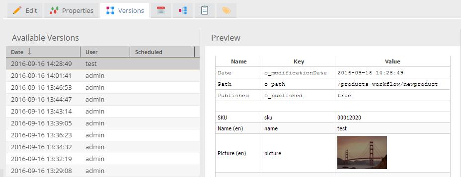
PIMCORE Backend UI where versions are listed

Scheduling: The element types in PIMCORE, documents, assets and objects implement a scheduler. It gives the ability to create tasks including publish, un-publish, delete and publish version.

As the name clearly suggests scheduler lets you choose the date and time for an action to be performed on a particular element. In the PIMCORE backend UI, you can look for the calendar icon (see in the image below). Here, the task can be added with date and time. The scheduler will then perform the task at the date and time chosen by you.

This helps the ecommerce company manage the products efficiently and somewhat automatically.

Phew! One doesn’t even need to be present there to make things happen. Schedule it and it will be done at the time of your choice!

PIMCORE Schedule

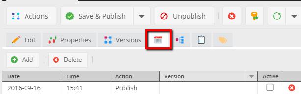
Tasks like publishing/un-publishing can be scheduled here

Notes and Events: There are a few changes or events on the elements that are independent of versioning. These changes are logged by Notes and Events module of PIMCORE.

Creating Notes and Events Using API

Notes and Events PIMCORE

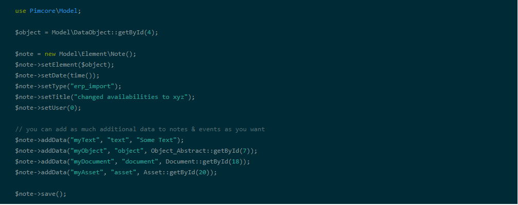
This is how the entry will look like

Notes and Events2

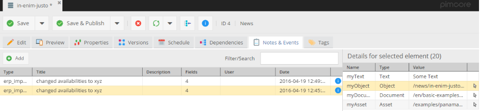
This is not be confused with versioning. Some changes to the elements made by the marketers or changes happening during imports/sync do not have a direct impact on the data. However, they are important enough to be recorded. For all such changes, Notes and Events are used.

Properties: The PIMCORE elements may have their own custom properties. For instance, the document may need to show the sidebar, use additional style sheets or hide the navigation panel. These properties can be specified using this Properties feature.

When you have multiple editors on a PIMCORE installation, predefined properties are helpful. Using the feature, default value of each property can be defined. The productivity of the editors increase manifold as a result.

Properties PIMCORE
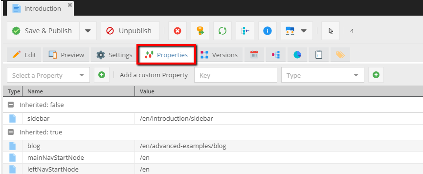
Defining Custom Properties of the elements from PIMCORE Backend UI

Tags: If you need to create additional classifications for any of the objects (stores, products, inventory etc.) you will need this module. Creating extra taxonomies for the objects makes it easy to filter them. These tags also act as an additional search criteria to an application.

Wrapping Up

The ecommerce development team touched upon almost every topic to give a detailed insight into PIMCORE capabilities as a PIM/DAM solution.

The blog also introduced the services and feature set of PIMCORE that have been designed to de-clutter and centralize the product information.

Hope the blog quells a lot of doubts about PIMCORE. We will be back with more such insightful blogs on PIMCORE. Watch out for this space!