×

Happy to Help!

This website doesn't store cookies. Enjoy the experience, without worrying about your data!

Great, thanks!

Monthly Archives: October 2018

  • 0

Hardware Design Guide for IoT Projects (Part II): Security, FOTA & Regulatory Compliance

Category : Embedded Blog

In this Part II of the IoT Hardware Design series, our focus will be on other significant design factors such as Security, FOTA , and Compliance Certifications.

Also read: Hardware Design Guide for IoT Projects (Part I): IoT Sensor Nodes and Gateway Devices

Let us dive deep into them!

  1. IoT Hardware Design for Security:

    Your IoT project design must include robust security mechanisms to safeguard the IoT system and data, from any unauthorized access and other security threats like IP theft, malware attacks and more.

    Let us look at some of the common hardware security mechanisms in practice today:

    • Root of Trust: A Root of Trust (RoT) is a set of functions (software codes) that are hardened into a hardware module like Hardware Security Module (HSM). This stores the keys to encrypt and decrypt data, and create digital signatures.
    • PUF for Data Security: Data security can be ensured through public and private key mechanism. In order to ensure that these keys are generated from a secure source, you can select hardware devices with a Physically Unclonable Function (PUF).

      Under the PUF scheme, a unique key is generated depending on the unique properties of each piece of silicon.

    • Board level and chip level security measures help to protect the devices against tampering, IP theft, reverse engineering attacks etc.
    • Hardware security against Differential Power Analysis ( DPA) attacks: Often electronic devices are prone to DPA attacks, whereby a hacker can calculate the power consumption of any hardware device to extract cryptographic keys from the device.

      Using hardware devices with DPA licensed countermeasures in your IoT project is a foolproof method to ensure high-end security of your devices.

    IoT Hardware Design

    Image Source: iStock
  2. FOTA for Remote Device Management:

    In IoT systems, Firmware Over-The-Air (OTA) is a popular technique for remote and reliable management of field devices and applications.

    You can enable Firmware Over-The-Air (OTA) update in IoT devices either by designing  a customized FOTA module from scratch or use any of the managed platform solution for OTA firmware systems

    • In a custom built FOTA solution, you can plan the scheduling, release, recovery, reporting of firmware images; manage the firmware versions; choose the hardware, device interfaces and software for enabling FOTA- based on project requirements and BOM costs..
    • The managed platform based solution comes with in-built hardware , software tools, and takes care of system firmware, device grouping, event logging – among others.

    Also read: The process details of the FOTA update installation onto the target devices.

    FOTA Automotive

  3. Regulatory Compliance & Certifications:

    The rush to meet the functional requirements combined with the pressure for reducing the time to market , most often, leads the project development team to overlook the compliance and certification regulations.

    However innovative your application might be, if it doesn’t meet the certification and compliance regulatory requirements, it is not destined to see the light of day.

    The Product certification and regulatory compliance process must be an integral part of the IoT hardware design phase. You must check that each of the component you pick for your IoT design meets the essential regulatory standards and certifications such as Restriction of Hazardous Substances (RoHS) Directive, Federal Communications Commission’s (FCC) regulations, EMC/EMI compliance – to name a few.

  4. Choosing Hardware for Prototype vs Production:

    Selecting hardware for prototype development is altogether different from choosing hardware for production. The objective of the prototype development usually is to demonstrate the most essential and viable functions.

    On the contrary, at the production stage your focus is on factors like future scalability, ease of integration, tolerance to extreme environment conditions, hardware warranty , BOM cost– to name a few.

    A clear definition of prototype and production goals before the IoT hardware design stage will help you make a wise selection of components for IoT sensor nodes and IoT gateway.

    At the prototype stage , you can go for off-the shelf hardware platforms with added features like breadboard-able headers, USB connectivity, onboard antenna.

    For example,  Particle’s Electron is an Arduino-compatible microcontroller with an integrated cellular modem and can be used for faster prototype production.

    And based on the prototype evaluation and business estimates, you can for an off-the shelf hardware boards & components or custom designed ones or have a mix of both.

Hope you liked this blog series on IoT hardware design considerations. If you are looking for a detailed support for IoT project design, contact our product engineering experts.


  • 0

Hardware Design Guide for IoT Projects (Part I): IoT Sensor Nodes and Gateway Devices

Category : Embedded Blog

There is no substitute to the ‘in-depth understanding of the business requirements’, if you aspire to deliver a robust hardware design for your next IoT (Internet of Things) Project!

We will allow you some time to imbibe the following words of wisdom from our veteran and highly respected Hardware Design Expert – Mr. Raghavendra (Technical Manager, Embitel Technologies)

In hardware designing, everything boils down to a clear understanding of the customer’s business requirement. You have to take care of the minute details of component and data specification and ensure that it corresponds to the final goal. You should not be selling him an elephant when he asked for a fish.

He shared with us that before starting with hardware design of an IoT project, he makes sure that the team has all the answers for the following important hardware design considerations:

  • What are the physical signals that need to be measured?
  • How frequently we need to collect signals and how fast the data should be exchanged over the network?
  • Should sensors be connected to the cloud directly or via gateway device?
  • How much memory is required?
  • And more!
Encrypted

Image Source: Encrypted.com

With this, Raghvendra (known for these no-nonsense talks) nudged us in the right direction for our search for critical hardware design aspects.

This blog can serve as a ‘Hardware Design Guide’ for your IoT (Internet of Things) projects. Read along for more details!

  1. Factors Critical to Hardware Design of IoT Sensor Nodes:

    An IoT sensor node consists of sensor device, microcontroller, communication interfaces, power management module and other peripherals

    Let’s discuss the critical hardware design decisions that you may have to take and factors that influence the design:

    • First step is evaluation and selection of an appropriate sensor. Here are the factors/specifications that will have an influence on your decision
      • IoT Sensor resolution: This determines the smallest measurement that a particular type of sensor can reliably detect.

        Type of sensors required: One can integrate either a digital or analog sensors in the hardware design. If you are using an analog sensor, you must also consider components for signal conditioning and signal processing in your design.

      • In such cases, the sensor circuit will also have to include either analogue-to-digital converter (ADC) or Sigma-Delta modulator.

      • Sensor Nodes within an IoT network are expected to transmit 8 to 16 decimals of data in one millionth of second. And choosing a sensor with required data throughput is essential for efficient operations.
    • Microcontrollers: The selection of industrial grade microcontroller is done after a careful evaluation of the business requirement (time and cost of project design) and functional factors that include:
      • Algorithms: A microcontroller uses certain algorithm like ‘Random Number Generation’ algorithm to process sensor data into analog or digital format. So, you need to evaluate the algorithm supported by the particular microcontroller before choosing it.
      • Security: Using a microcontroller with built-in hardware Crypto engines, such as Data Encryption Standard (DIS) and Advanced Encryption Standard (AES) engines, helps to ensure a secure transmission of data from sensor nodes to the IoT network.
      • Power Consumption: Choosing low power microcontrollers helps in optimizing the overall power consumption. One can evaluate microcontrollers specifically designed for ultra-low-power applications, such as TI MSP430 or CC2650 wireless microcontroller.
    • Communication Interfaces: Most of the IoT applications require sensors that use low-power wireless communication modems like NBIoT, LoRA, 4G LTE Cat-M1 for communication.
    • Power management: The sensor nodes are designed to last for years. And this depends on the power source of the sensor nodes. One can choose low power batteries such as CR2032 lithium-ion coin-cell battery, as it outputs a constant voltage, is low-cost and offers a battery life of greater than 10 years.
    • Additionally, one may integrate nano-timer such as TPL5110 to optimize the power consumption, as the sensor nodes switch between wake-up and sleep modes.
      IoT sensors

      Image: IoT sensors used today are numerous in types ; Source:IoTOne

    You may read about some common type of sensors – IR sensors, proximity sensors, used in industrial automation systems here in detail.

  2. I

  3. Hardware Related Factors that influence your IoT Gateway Design:
  4. An IoT gateway could either be a simple gateway device that executes core  functions such as protocol compatibility and device management; or an Advanced edge gateway devices with additional data analytical capabilities.

    Designing an IoT gateway hardware would thus depend largely on the type of functions it is expected to perform.

Here is a glimpse of some common hardware design parameters that will influence your IoT gateway development

  • Microcontoller v/s Microprocessor: An IoT Gateway with microcontroller is ideal for small to a medium scale application, while you may need a gateway with a processor, if the gateway has to perform more complex functions such as data analysis and storage.
  • Power Consumption: This will depend on the complexity of your IoT hardware & power requirements of other components of the circuit. For example, if your design consist of a number of external devices such as display screens, camera – the overall power consumption might go up.
  • Energy from renewable sources: If your device is being powered by renewable energy sources like solar, your design will have additional components. For example, you would need as 2 stage solar converters ( MPPT based converters and DC –DC/DC-AC converters), power management ICs that are compatible to the solar panels to sufficiently charge your devices.
  • Processing Power & OS: This becomes a critical factor if you are deploying Gateway with Edge Analytics capabilities. This is because for data processing, IoT Gateway design should include necessary amount of  memory, and a multi-core processor. The OS chosen should have a higher context switching rate and real-time response rate.
  • Memory : Most of the gateway devices used in critical IoT systems such industrial automation, fleet management are based on hard real-time controllers and hard real-time schedulers. In such cases , data is stored in RAM memory. Other memory types used in a smart IoT gateway device would include NOR Flash, Flash boot .
  • As mentioned before, the memory requirement in the design increases, if the IoT gateway device is expected to perform processing and data analytics.

  • Communication/ Networking Modules:
    Within an IoT network, devices or systems ( sensor, gateway, end devices) can communicate either through a Wireless ( Bluetooth, Wi-Fi, Cellular) communication channel or  a Wired Connection.

    Your IoT design will have to include Wireless communication modules when when the devices/systems are located in close proximity and there is little scope for setting up hardware installations required by a wired connection. (installing Ethernet cables, routers etc.) .


    Communication Interface Type of Wireless Communication
    Sensor/Device to Gateway Cellular(4G), NBIoT, ZigBee, Bluetooth
    Device to Cloud WiFi, Cellular(4G), 6LowPan, LoRa


    A wired communication is usually deployed for long range communications. Ethernet, with an average speed of 10 Mbps, is one of the most used wired communication protocol for connecting devices for applications like industrial automation.

    Fast Ethernet (IEEE 802.3u) and Gigabit Ethernet(IEEE 802.3z) with transmission speeds of 100Mbps and 1000Mbps are some of the widely deployed wired connection interfaces.

    Many of the standard IoT hardware boards such as Raspberry Pi, Arduino, Beagle Bone are embedded with a set of communication interfaces ( UART, USB, Bluetooth ,  Wi-Fi, Ethernet port). You can also create a custom hardware board wherein you include only the selected communication interfaces that your project needs.

Hope you liked this blog. If you are looking for a more detailed and personalized support for IoT project design, please get in touch with our product engineering experts.


  • 0

Challenges your Automotive Team may Confront During Migration from CAN 2.0 to CAN FD

Category : Embedded Blog

Imagine a scenario where a car driving on a slippery road loses traction and starts to skid. In such an emergency situation, the built-in Electronic Stability Program is required to get into the action.

This program will need to detect the vehicle speed and the torque on each wheel, at real-time, to take corrective measures.

CAN 2.0 protocol, with its 8-bit data rate and lesser payload capacity, may not be the best solution for such applications.

For such data-intensive applications that call for faster response times, CAN FD (Flexible Data Rate), a successor of CAN 2.0 protocol, has been developed.

In the era of ADAS, Remote Diagnostics and other connected car applications, the need for migration to CAN FD is being felt by technology teams across the globe.

This transition has its own set of challenges, which we will discuss in detail.

So before kick-starting your CAN FD migration project, do read about these personal experiences of our Automotive Product Engineering Services team.

Migration of Existing Application from Classical CAN to CAN FD

Before we start to explain this scenario, it is important to highlight the architectural difference between CAN 2.0 and CAN FD.

The increase in data transfer rate and payload capacity in CAN FD is brought about by the change in the data link layer and the physical layer. The CAN messages that had to be split because of 8 byte payload limitation in CAN 2.0, can be combined into one message in CAN FD protocol.

Major Differences in CAN 2.0 and CAN FD

Classical CAN or CAN 2.0 CAN Flexible Data
Data bit rate is max 1 Mbps Max data bit rate is 8 Mbps
A maximum of 8 bytes of data can be sent in one frame without Transport Protocol 64 bytes of data can be sent in one frame without the TP layer.
Multiple CAN nodes can broadcast message frames. Only one node transmits at a time; one of the reasons for increased bit rate
No BRS or FDF to switch the speed to higher or lower levels Bit Rate Switch (BRS), Flexible Data Rate Format (FDF) and Error State Indicator (ESI) together ensure higher speed.
Cyclic Redundancy Code contains a 15 bit code CRC field has 17 or 21 check codes
Less secured due to less data payload capacity Enhanced security of data as CAN FD data can be encrypted using the extra memory

For an application to be migrated to CAN FD from Classical CAN, the data link layer needs to be first made compliant with CAN FD.

The data link layer comprises of the ISO Transport Protocol (TP) layer as well as the CAN FD device drivers.

Hence, the migration in this scenario is a 2-step process.

  1. ISO Transport Layer Development Based on CAN FD Document

    In case of CAN 2.0, the transport layer can receive or transmit data length in tune of 256*16. However, CAN FD transport layer is capable of receiving/transmitting data length of much larger size i.e. 232-1.

    Hence, to support the 64 data bytes payload and CAN FD message frames the automotive software team will have to make relevant changes in the Transport Layer. The changes in the TP layer is made according to the standards mentioned in the CAN FD documents.

  2. Developing the CAN FD based drivers for the microcontroller family

    In order for the microcontroller to receive and transmit CAN FD data frames, the CAN FD drivers are written w.r.t the MCU family. The Bit Stream Processor is the component tasked with receiving/transmitting CAN FD frames. Separate drivers are required for each of these components to function.

Need for External CAN FD Controller

At times, there are certain legacy microcontrollers that do not support CAN FD protocol.

One solution is to replace the entire MCU with a CAN FD supported microcontroller. However, changing the entire MCU hardware may not be a viable option. This would mean following the entire process of device driver development, integration and testing. The escalated cost and time-to-market can have a major impact on the ROI.

A better and one of the most widely used methods to make such systems CAN FD compatible is to add an external CAN FD controller. These controllers act as slave devices and communicate with the vehicle network on behalf of the main control unit.

The automotive ECU communicates with an external CAN FD controller using Serial Peripheral Interface (SPI). The communication starts by application asking for some vehicle parameter say engine speed. The transceiver in the MCU will interface with the external CAN FD controller.

The external controller, on the other hand, will act as a CAN FD engine. It will process the CAN messages from the vehicle and pass any relevant information to the MCU.

The role of the automotive software developers here is to develop the SPI based drivers to help the MCU communicate with the external CAN FD controller. Device drivers, as well as, low-level drivers also need to be developed for this slave device.

Mixed Networks and Partial Networking

Mixed networks where both CAN 2.0 and CAN FD nodes exist, on the same network bus, are quite common. Although CAN FD transceivers are compatible with Classical CAN, the data link layer is not.

This implies that if a CAN FD node sends a signal, the CAN 2.0 node will not be able to receive it, causing error and interruption in the communication.

One of the most widely used methods to fix this compatibility issue is partial networking. The partial networking functionality makes use of a CAN transceiver standard, called CAN with selective wake.

When a CAN FD is communicating, the CAN 2.0 nodes are passive i.e. invisible to the network. This condition is akin to putting the CAN 2.0 nodes to sleep while CAN FD communicates. However, the CAN 2.0 nodes are not completely inactive; they are selectively awake.

A Partial Networking (PN) transceiver comes into picture in such a scenario. This transceiver keeps the CAN 2.0 disconnected from the network during CAN FD communication. As soon as a valid CAN 2.0 wake up message appears, the transceiver will wake up the CAN 2.0 nodes and route the message to them. It is interesting to note that this wake up message frame is sent by CAN FD node itself.

“There is a power factor associated with partial networking too. When the CAN 2.0 nodes are made passive, they enter a low-power mode. In electric vehicles, this helps save a fair amount of battery power as well. “

Conclusion

CAN FD not only ensures high speed data transfer but also does it securely. With the emergence of concepts such as telematics, connected cars, and remote ECU reprogramming, security has been a major issue. Also, the update size for certain applications have become larger and frequent.

CAN FD is able to handle both these issues efficiently. And with swift migration of applications to CAN FD, the complete transition from Classical CAN to CAN FD will soon be a reality.


  • 0

Decoding the Technology Architecture that Powers SAP Hybris B2C Accelerator

Category : ecommerce-insights

 
During the times when online commerce had not become omnipresent, the interactions at limited customer touch-points were transactional and simple.

Simplied Ecommerce Transactions-Embitel-Bangalore-Hybris

(Image Source – SAP Hybris)

With the dawn of Omni-Chanel Commerce, these interactions at multitudes of customer touch-points are now customer-centric and way more complex!

Complex Ecommerce Transactions-Embitel-Bangalore-Hybris

(Image Source – SAP Hybris)

This complex system comprises of data-sources which are discreet and provide data items which are pieces of the puzzle that need to be put together.

For such systems which are being fed data from ERPs’, CRMs’, POS and other store systems, a solution which provides a uniform view of the products and processes is the need of the hour!

We sat down with our SAP Hybris consultants to understand the promise of ‘Single Source of Truth’ that is being enabled by Hybris Ecommerce Solution. This blog is our pursuit to understand the technology architecture that powers this solution and learn what a B2C accelerator is?

single-source-of truth-sap-hybris-embitel-bangalore

(Image Source – SAP Hybris)

Technology Architecture that Powers Hybris Omnichannel Commerce:

The following is the single-stack technology architecture that enables a Single View of Products, Customers, and Orders:

architecture diagram-SAP-Hybirs-Embitel-Bangalore

(Image Source – SAP Hybris)

Let’s decode these components one at a time!

  • Commerce channels or Customer touch-points: In this hyper connected world, it is essential for the brands to register their presence at various touch-points. However, it is also imperative for the brands to deliver consistent customer experience across all these touch-points.

    In technology terms, such consistency is possible only if your store-fronts facilitate Single View of products and services.  This means that irrespective of the touch-points, a customer should be able to view consistent product pricing, product description and other related information across all the channels.

    This is made possible by the underlying layers of the architecture.

  • OmniCommerce Connect: This layer consists of web-services based APIs’ that serve as an interface between the channels and the back-end modules.
  • Modules and Accelerators: Hybris Accelerators are software packages that support functions and features that are specific to a business model (B2C, B2B, B2B2C) and/or an Industry Domain (Telecommunication, Retail, Heavy Equipment, Consumer Goods and more).
  • During SAP Hybris implementation, based on the project requirements, your Hybris Technology Partner would assist you in defining the architecture and identifying the appropriate accelerators.

    Modules are the software packages that are available as bundled solution for all the accelerators. These are sets of common features and functionalities that are necessary for any Ecommerce Implementation (e.g features like Store Locator, Pricing, Checkout and others)

  • Order Management and Content Management: Both these modules are an integral part of any SAP Hybirs Omnichannel Commerce implementation.

    Content Management consists of Product Content Management (PCM) which handles all the information related to the products and Web Content Management System (WCMS), which manages data related to UI/UX of the store-front

    Order Management System (OMS) deals with all the features that are necessary once an order is created in the system. OMS facilitates features like order creation, cancellation, refund, partial refund and more.

What is a B2C Accelerator?

B2C Accelerator is a fast-track solution that helps your brand to become omnipresent. This is a ready-to-deploy software package with customizable web store-front templates and essential business process tools that help you reduce time-to-market and cost.

A B2C accelerator is a base-solution that enables you to build a customized B2C interface with reduced Total Cost of Ownership (TCO)

The following are some of the critical components of a B2C Accelerator:

components of a B2C Accelerator

(Image Source – SAP Hybris)

  • Interaction Layer: This layer deals with the human interaction with the B2C Accelerator. Some of the important components of this layer include Cockpits, Hybris Management Console (HMC) and Web Services.

    Cockpits are set of proprietary tools that a Hybris B2C Accelerator provides to business users for performing tasks and actions related to Product management, Warehouse management, Content Management and more. This helps in reduction of maintenance cost (post implementation) as no change in code is needed and there is no downtime.

    Hybris Management Console (HMC) is a centralized hub for all administrative tasks, actions and processes. These admin related activities are necessary to ensure seamless day-to-day business operations. Generally, only Hybris Admins have access to to HBC.

    Web Services are communication interfaces between the Hybris B2C Accelerator and third party external systems like payment gateway, shipment plugin and more. Web Services also serve as an interface with the Mobile Application.

  • Object Models Layer: This layer consists of Hybris ServiceLayer Framework along with Business and Infrastructure Services.

    This layer deals with all the Java APIs’ for objects in SAP Hybirs Commerce. These object models are generated based on types.

    Business Services manage API related to Pricing, CMS and more; while Infrastructure Services manage API related to caching, security, transactions and session

  • Hybris Persistence Layer: The Hybris Persistence Layer manages abstraction from database, caching and clustering. This makes this B2C Accelerator a database independent solution.

To learn more about B2C Accelerator and understand how it can add value, please get in touch with our Hybris Consultants at sales@embitel.com


  • 0

Firmware Over-the-Air (FOTA) Update and Bootloader Development for an Electric Vehicle


About the customer

Our customer is a leading Electric Vehicle OEM. Before this project, we have had the privilege of partnering with the same customer for other product development programs, mostly in the EV space.


Business Challenge

During the design stage, our customer realized the need for remote vehicle diagnostics and ECU re-programming for an Electric Vehicle Control Unit (ECU) product.

Integration of Firmware-Over-The-Air (FOTA) software and hardware could facilitate this requirement. Fully aware of our competencies, the customer was confident to partner with us for this FOTA project

After a series of discussions, it was agreed to develop a FOTA system with two microcontroller platforms – one for interfacing with the cloud backend to download the new update package and the other for interfacing with vehicle control units over CAN to fetch vehicle related data.

This complex system was to be built within a very challenging time frame. As we had already had several ready-to-deploy stacks- UDS, CAN, BSPs etc. as well as all the requisite skill sets, we had the confidence of delivering quality products within the stipulated time-frame.


Embitel Solution

After finalizing the project scope, our automotive software development team swung into action. The software architecture was prepared with clearly defined layers.

FOTA_System_Architecture_Case Study

Following were the deliverables we planned to provide:

  • FOTA enabled Bootloader to be implemented into the Application Processor (Sierra Wireless),
  • Bootloader software for a separate microcontroller called the Vehicle Control Unit (NXP),
  • Hardware Abstraction Layer (HAL), CAN/LIN drivers ( to facilitate communication between vehicle ECUs ),
  • HTTPS, MQQT protocol implementation (for secure connection with the cloud backend),
  • Low-level device drivers (SPI, UART, timer etc),
  • GPS & GSM modules and external memory module,
  • UDS software stack for remote vehicle diagnostics,

Here is an overview of the FoTA system we developed:

FOTA_Diagram_ME_Electric Vehicle

Our experience in working on a plethora of microcontroller platforms like Freescale, Renesas etc. ensured that we had reusable Board Support Packages and device drivers ready for deployment.

We performed the required customizations in these components, for seamless integration with Electric Vehicle ECUs. As agreed-upon, we also provided post-delivery support in the event of production environment issues.


Embitel’s Impact

The biggest impact was the reduced time-to-market, as this was a major concern for the customer.  We were able to deliver the project in 4 weeks.

Our reusable stacks and software packages were able to reduce the development time by a whopping 60%.


Tools and Technologies

  • Server for testing- Microsoft Cloud
  • IDE- Code Warrior and IR Embedded Workbench


  • 0

Development of AIS 140 Compliant FOTA Enabled Bootloader Module for a Tier-1 Supplier

About the Customer


Our customer is an Automotive Tier-1 supplier, specializing in vehicle control systems and components.

Keeping up with their commitment of delivering innovative solutions for the automotive industry, they planned to introduce FOTA (Firmware Over-The-Air) update feature in their product lines.

The basic idea was to enable the automotive control units to install software updates from the Cloud Server in real time. Eventually, the customer also wanted the product to be AIS 140 compliant.

Business Challenge


Customer’s project roadmap, of integrating FOTA in an Automotive Electronic Control Unit (ECU), was confronted with following challenges:

  • need for a robust FoTA enabled Bootloader solution
  • lack of expertise and experience in AIS 140

A CAN/LIN based Bootloader  was required for application and ECU reprogramming over the air.

The bootloader was required to be a part of the telematics unit that is tasked with ECU reprogramming over the air and facilitating remote vehicle diagnostics. The expertise in application processes development and testing for FoTA was also required.

A Product Engineering Services partner with ready-to-use components like Board Support Package (BSP) software and low-level device drivers for popular Microcontroller family was sought by the customer.

Having 12+ years of experience in CAN, Bootloader, and vehicle diagnostics, Embitel was chosen to come on-board for this project.

Embitel Solution


Before embarking on the solution development, we had several rounds of discussion to understand the pain points of the customers. We also analyzed the components that would need to be built from ground zero and found out opportunities where our re-usable components could be integrated.

The system architecture for the enablement of FOTA included the following components:

  • Telematics Control Unit,
  • Vehicle control unit,
  • Bootloader for telematics and MCU,
  • low-level device drivers,
  • and the Application Layer.

Our solution comprised:

  1. Telematics Unit (Renesas) to connect to the server using HTTPS and MQQT protocol
  2. CAN/LIN based Bootloader to flash the vehicle ECU
  3. CAN/LIN drivers to help the vechicle control unit collect data such as engine speed, vehicle parameters etc. from vehicle interface
  4. Low-level device drivers, SPI and UART drivers to facilitate communication between telematics unit and microcontroller.
  5. Remote diagnostics with UDS
  6. Application processor from Telit and Sierra Wireless with GPS and GSM modules for remote server connection; external memory for storing the update.

Apart from them, we deployed our production grade reusable components such as Board Support Package (BSP) software with flash drivers for Renesas Micro and Freescale MCU family.

Rigorous testing was performed on both internal servers and servers provided by the customer. We ensured that the components are AIS 140 compliant, as defined in the project scope. Post-delivery support was also provided by our team.

Embitel Impact


We were able to deliver the project in a very restricted timeframe. Our expertise in providing assistance for AIS 140 compliance was a great value add for the customer.

  • 60% of development time was reduced due to our reusable board support package and flash drivers.
  • Project was delivered in 4 weeks.

Tools and Technologies


Server for testing- Microsoft Cloud

IDE- Need to confirm with Suresh; will update


  • 0

Understanding Embedded Electronics Behind Solar Based Charging of Electric Vehicles

Category : automotive-insights

Very recently, Electric vehicles have been rapidly gaining popularity as they are an eco-friendly alternative to gasoline driven cars. According to a report by International Energy Agency, the global Electric Vehicle ownership has shown a rapid growth of 54% from 2016 to 2017.

Studies also suggest that, Electric Vehicles (EV), as compared to fossil fuel cars, have considerably lower greenhouse gas emissions that can even be brought down to zero, provided green electricity is used for charging of EVs’.

The access to green electricity is also becoming a reality due to the paradigm shift in the global energy generation landscape. At the world stage, a lot of innovations and investments are happening in this space, and specifically in the solar power generation sector.

The global advisory firm, DNV GL in its Energy Transition Outlook 2018 has reported that 80% of global electricity production will be powered by renewable energy sources (solar energy and wind power).

Off late, tapping the abundantly available solar energy and its application as a power source for Electric Vehicles has become a necessity rather than a mere option for combating the hazards of environmental pollution. One of the most powerful use-cases, in this context, is ‘Solar Powered’ Electric Vehicle Charging Stations. Many stakeholders are already looking at Solar Powered EV Charging as the Next Big Thing!

So, What is the technology, behind the scenes, that is playing the role of an enabler? What are the key benefits of using solar PV panels for powering electric vehicles?

This is our quest for answers to these questions!

Solar Energy Charging

Image Credit: beagreencommuter

Embedded Electronics Enabling the Usage of Solar PV System for EV Charging

Solar Panel charging installations for Electric Vehicles available today can be broadly categorized into:

  • Mobile Solar Charging systems that includes the rooftop solar panels used for charging the batteries of an electric Vehicle.
  • Fixed Solar powered charging installation, a ground based installation (grid based or off-grid) that includes direct charging installations/devices available at EV charging stations.

In this blog, we will talk about the technology behind the off-grid fixed charging installations. At its core, a solar energy charging system converts the photovoltaic energy from the solar panels into DC electrical energy; which is fed to the EV batteries.

Let us look at main components of a solar energy charging system for Electric Vehicles:

  1. Solar PV Panels: A photovoltaic (PV) panel harnesses the solar radiation into electrical energy to be supplied to the electric vehicle batteries. In fast EV charging stations, large array ( ~300) of electrically connected solar panels would be installed to generate the required power to charge electric cars in a day.

    The angle of solar panel is one of the crucial factors in deciding the output efficiency of these panels. The other factors being the latitude, longitude and weather conditions.

    The solar panels are attached to moveable, motor-controlled solar trackers. Based on the inputs from the microcontrollers, these motor-run trackers move the solar panels axis to receive maximum sunlight any given time in a day.

  2. Microcontrollers: The microcontrollers (such as Texas Instrument C2000, NXP P89V51RD2) used in a typical solar PV charging system have the responsibility of :
    • Ensuring maximum efficiency of solar power generation through the MPPT controllers.
    • Storing the extra energy generated from the solar PV panels into storage battery cells which.

    Additionally, the microcontrollers are programmed to control the motor using a Pulse Width Modulation (PWM) technique to align the panels for maximum power generation.

  3. Motor to control Solar Panel Axis Rotation: A bi-directional motor is used to control the solar trackers so that the panels are tilted at an angle where they receive the maximum sunlight at any given time in a day. The real-time information about maximum solar radiation is obtained through the Solar Position Algorithm.

    The Solar Position Algorithm calculates the sun’s position based on the azimuthal and elevation values, based on the time, date and location of Earth. This information is used by the central microcontrollers to control the motors to rotate the panels at specific angles at which they would receive the max. solar radiation.

  4. DC-DC converter with MPPT: An electronic DC-DC converter helps in converting the high power generated from solar panels to required EV battery voltage. These DC-DC converters use Maximum Power Point Tracking (MPPT) to support the PV panels to operate at the maximum power.

    Maximum Power from solar radiations is inherently non-uniform in nature and varies with temperature and time in a particular day. The DC-DC converter offers an interfacing between the photovoltaic panel and the load to achieve maximum power transfer without loss. The MPPT controller is connected to the output of the solar PV panel.

    In a typical photovoltaic generating systems such as the solar EV charging system, an MPPT can be enabled ( within the microcontroller) through :

    • Software implementation  as part of the firmware, or
    • As part of hardware implementation through System –On-Chip ( SOC) with certified ICs such as TI C2000.

    The MPPT controller takes in higher voltage DC output from panels, and evaluates the best possible value of power from the panel to charge the battery and converts the power into optimized voltage levels to get maximum Ampere values.

    Flowchart-of-DC-DC-converter

    Flowchart of DC-DC converter with MPPT.  Image source: rroij
  5. Communication Interface between the EV battery systems and charging system: The battery monitoring system (BMS) of the electrical vehicle should communicate with the solar powered charging system to ensure an optimal charging without fail. Most often the charging devices communicate with the BMS of the electric vehicle either via a CAN BUS or Power Line communication. During this handshaking, following information is exchanged between the two systems:
    • Maximum capacity of the vehicle battery
    • Rate at which current is transferred
    • Temperature and other parameters related to the EV batteries
  6. Interface: Most EV charging stations come with a Human-machine Interface to display various parameters including solar energy capture, the energy consumed by the EV battery while it is being charged. The number of display options on the HMI may vary with the manufacturer, to enhance the user experience.
  7. EV Battery charging equipment: The Society of Automotive Engineers (SAE) specifies 3 levels of charging standards for electric vehicle charging equipment: Level 1, Level2 & Level 3- where the ‘levels’ indicate the charging power.
    • Level I Charging: A level 1 charging equipment uses standard household power outlet with 120 V circuit. Fully charging an EV using an L1 Charger can take 8 to 12 hours or even more, depending on the EV battery type. A Level 1 charging is best done at home overnight, when the vehicle usage is the least.
    • Level II: A level II charging describes a 240 volt AC charging and is commonly used for daily commute. An LII Charger can fully charge an EV in 4 -6 hours, depending on the EV battery type. The LII charging equipment can be found in public spaces, residential settings, and commercial areas to facilitate easy EV charging.
    • Level III- DC Fast Charging: A level III charging equipment charges an EV through a high-voltage DC chargers (480 V plug) and supports charging up to 500 volts. In a fast charging mode, an L3 charger can supply an EV with 80% of charge in just twenty to thirty minutes.
      Level-Charging

      Image Credit: InsideEV

Key Benefits of Using a Solar PV Panel as an Energy Source for EVs

At this stage, we are witnessing the onset of widespread installations of Solar Powered Charging Stations across various cities of the world. Reasons for this growth in numbers are many. Let us look at some of the tangible benefits:

  • About 80% of a solar panel module can be recycled using advanced end-of-life recycling techniques. The end products of this recycling can be used for more productive processes. The International Renewable Energy Agency (IRENA) has observed that various materials recovered from solar panel recycling could be $450 million by the end of 2030.
  • The average lifespan of a solar panel manufactured today, is more than the 20 years. Contrary to the conventional batteries and inverters that need a replacement every 5-20 years of installation.
  • Improvement in technology is enabling solar energy to chart new records in terms of power generation and capacity.
  • Solar Energy is one of the cleanest options for fueling the electric cars.
  • Solar panels installed at homes can help significantly in saving electricity costs through a controlled charging schedule.
  • Prices of solar installations have reduced considerable over time, encouraging more people to invest in one of the most popular forms of renewable energy.

Solar Energy and EV: Steps taken by Governments and Automotive Companies

Over the past few years, many government bodies, automotive manufactures and other industry stakeholders have come forward to explore the new opportunities offered by Combining Solar and Electric Vehicle Charging.

Together they aim to not only encourage wide usage of EVS and solar PV Panels, but also find a sustainable alternative to the world’s fast existing reserve of fossil fuels.

Let us have a glimpse of some of them:

  • Aimed at fully tapping the Solar+EV opportunities, The U.S. Department of Energy’s National Renewable Energy Laboratory has decided to work with Great Plains Institute to explore the market-driven opportunities of combining solar energy generation for controlled EV charging.
  • GCL, a leading solar equipment manufacturer in China is building a solar production base, estimated to be around $721.19 million in Jiangsu province. In order to support country’s EV revolution, the firm plans to collaborate with auto manufacturers to join the project and construct EV facilities in the province.
  • India plans to achieve 175 gigawatt (GW) of renewable energy capacity by 2022 – of which 100GW will be from solar energy sources, as part of the global climate change accord. The country seems to be tapping its solar energy generation capacity and harness it for charging up its EV revolutions. In a recent development, a solar powered DC charging station was installed in Mumbai, India – a first of its kind in the country. Developed together by Magenta Power and Exicom Power Solutions , the project aims to install more (100s) EV charging stations along Mumbai, to begin with, by the end of 2018.

Concluding Thoughts:

Global trends indicate that both the EV and Solar industry has been witnessing an exponential growth over the recent past. For example, the US has approximately 250,000 EVs and about 500,000 solar rooftops, and both industries are still growing exponentially.  While challenges exist in the way for the solar energy based electric vehicle charging systems to become a mainstream option, government policymakers and auto-manufacturers are exploring the feasibilities to address them.

Thus, the combination of Solar Energy and EV is mutually beneficial one wherein each one can open up new avenue of growth for the other, while also helping in reducing the eco footprint, quite significantly. Additionally, the PV-EV synergy is expected to open up new windows of business opportunities in the near future throughout the value chain while keeping up the clean energy commitment.


  • 0

Motor Controller Software, HAL and UDS Protocol Stack Integration for an Autonomous Headlamp

About the Customer:


Our customer is a leading manufacturer of Headlamp systems for Automotive. They have partnered with us as their Product Engineering Services provider, for prototype development of one of their ambitious Smart Automotive Headlamp product.

This Automotive Headlamp design facilitated the change in position of the Car Headlamps, with the help of sensors and motor control systems, based on the load and the elevation of the road.

Business Challenge:


Our customer is a pioneer in making Electric Headlamps for Automobiles.

However, for this next generation product development they realized the need for an experienced Product Engineering partner. The required skill sets comprised Embedded C, Device Driver development and comprehensive automotive domain knowledge.

Our Automotive team was tasked to design software algorithms that will enable headlamps to adjust automatically & focus in the right direction, based on the different states of the vehicle.

Embitel Solution:


After several rounds of discussion with the customer, the project scope was defined. Based on the discussion and our understanding of the project, we decided to develop our design based on NXP 32 bit microcontroller platform.

Getting the accurate pulse width modulation signal required algorithms to read the sensor data very precisely. Readings like the tilting angle and position from the sensors such as accelerometer and gyroscope also had to be analyzed.

Apart from the application layer (headlamp adjustment algorithms), low level device drivers and Hardware abstraction layer, were also designed. Their role was to facilitate communication between the servomotor and the application software.

We delivered a re-programmable unit which could be calibrated as per the production program.

Following is the software architecture diagram:

The final solution comprised:

Application software Development for autonomous electronic headlamp system:

  • Angular Velocity Algorithm for Pitch Calculation.
  • Level Controller- the motor drive algorithm that would drive the servomotor with pulse width modulation, PWM signals.
  • Parameter Configurations.
  • Self-Diagnostics to help the system find issues and report them.

Low level Device Drivers development:

  • Micro controller Unit.
  • Timer.
  • CAN drivers.
  • Pulse Width Modulation drivers.
  • Serial Peripheral Interface drivers.
  • Analog to Digital Converter.
  • Watch dog driver.
  • Non Volatile Memory (ROM).

Hardware Abstraction Layer:

  • CAN Interface.
  • Pulse Width Modulation HAL.
  • Serial Peripheral Interface HAL.
  • Analog to Digital Converter HAL.

Service and Diagnostics Layer:

  • Math utility (Filtering, Average etc.).
  • Safety features (CPU Overload, Stack over flow).
  • Scheduler (Non preemptive timer based).
  • UDS based Diagnostics Layer (ISO14229) & ISOTP (ISO15765).
  • Fault Code Memory (FCM).

Apart from the application software and device drivers, the deliverables also included:

  • Low-level documents.
  • High-level documents.
  • Test Plans and Reports.
  • Our Ready-to-deploy UDS based bootloader software for ECU reprogramming purposes.

Impact


We were able to provide the complete set of deliverables within the stipulated time. We integrated our ready to-deploy Bootloader software and UDS stack with the production grade prototype. This helped us reduce the development time and cost.

Our experience in working with motor control systems also came in handy while developing the leveler algorithms for the project.

Tools and Technologies Used


S32 IDE from NXP – For embedded C programming.

PE Debugger- For code debugging.

SCANoe–– For CAN Testing

BUSMASTER–Testing.

Motor– Servomotor for precise movement based on angular/linear position.


  • 0

Automotive Motor Control System: The Brain Behind the Brushless DC Motors in an Automotive Application

Category : Embedded Blog

In any Mechanical or Electronic system, where ever there is a continuous rotational motion involved, there is a Motor. And in the modern-day automotive, where comfort is as important as the driving efficiency, Motors play a pivotal role.

Be it the windows, seats, steering, turbochargers, ventilation flaps or brakes, there are Electric Motors to be found in each of these components. In fact, there are a few hundred electric motors in a passenger car. You see, they are called Motor-Cars for a reason!

The motors, however, don’t start and stop on their own. Like many other automotive components that are controlled by Electronic Control Units (ECU), there are also Motor Control Systems to drive a Motor.

To understand this system in detail, we met our automotive team members, who were more than eager to share their knowledge and insights with us.

While we had a basic understanding of Automotive Motor Controllers, we didn’t have the faintest of idea about how advanced these motor control systems have become. This blog is about sharing these learning with our community of Automotive Developers.

Different Types of Motors you would find in your Automobile

Our conversation with the Automotive Team began by discussing the various types of electric motors deployed in modern-day cars

During this discussion, we realized that Electric Motors have come a long way, as far as their applications in automotive industry are concerned. And this evolution is still on-going.

Many safety as well as comforting features in a vehicle, require Electric Motors. Depending on the applications, there are primarily 3 types of motors that are widely used in the vehicles:

  1. Brushed DC Motors: These DC motors have metallic brushes between the motor coils and the rotors that complete the circuit. There is no electronic component required to operate this motor. They are ideal motors for Power Window, Seating Control, and other such applications where mechanical parts are operated without any assistance of an electronic systems (like an MCU or a drive logic).
  2. Brushless DC Motors: These are one of the most widely used DC Motors. A brushless DC motor has permanent magnets as the rotors. As the current is passed through the motor coils (stator), the rotor being a permanent magnet starts to rotate. As there is no physical contact between the stator and rotor, a motor controller is required to alter the speed of the BLDC motor.
  3. AC Induction Motor: Most widely used in Electric Vehicle Drivetrain applications, an AC Induction Motor works on the principles of Faraday’s law of induction. There is a rotating magnetic field produced due to the alternating current in the coils. This moves the rotor. The speed of the motor can be altered by varying the frequency of the alternating current supplied to the motor.

Understanding the Anatomy of an Automotive Motor Control System

Business use-cases and applications of Electic Motors in automotive, called for systems which can control the motor according to the application-specific logic. For instance, a motor deployed in an Electronic Power Steering (EPS) system is required to alter its speed based on the torque applied by the driver on the steering wheel.

A motor control system is required to implement this logic.

This system is essentially an Electronic Control Unit (ECU) like all other ECUs in a vehicle. It comprises of a Microcontroller ported with the Motor Drive Logic (software) and integrated with some other Motor-Control peripherals (hardware).

The Motor Drive Logic is the software algorithm that drives the motor in the intended manner. The peripherals like gate driver IC, MOSFETS etc. are part of the control system that performs auxiliary tasks like error feedback handling, signal conditioning, current and voltage amplification. We will learn more in detail about all these components, very soon!

We were also introduced to how a Motor Control System works. But before we get started with this,.

Let’s first learn about the components of a Motor control system:

  1. Microcontroller: Microcontroller Unit (MCU) is essentially the component where the Motor Drive Logic is stored.

    For instance, in an electronic power steering application, a steering control algorithm will be stored in a microcontroller platform. The algorithm is used to vary the speed of the motor using Pulse Width Modulation (PWM) signals.

    Input and Output buttons can be interfaced with this MCU. PWM signal which is generated as the output and is interfaced with the next core component of the Motor Control System.

  2. Gate Driver IC: Gate Driver IC also known as a pre-driver is that next core component! It, receives the PWM signal from the MCU and amplifies it to make it suitable for the MOSFET.

    This was a little confusing for us because knowing that MOSFETs are generally used to amplify the voltage, then what is the purpose of having a Gate Driver IC in a motor control system.

    We were informed that there is a certain threshold voltage value that is required by a MOSFET to be able to function; Gate driver IC provides that threshold voltage. Also, there are some signal conditioning algorithms in the Gate driver IC that removes the noise from the signal and smoothens it.

  3. MOSFETs: These are field effect transistors that can amplify a few milliamps current to ten times and small voltage value to several hundred volts. As electric motors require minimal switching time in varying the current flow to the motor, MOSFETs are an indispensable part of the Motor Control System.
  4. Hall Effect Sensors: The role of Hall Effect sensors in automotive motor control application is to determine the position of the motor. It is essentially a transducer that will induce a voltage when the flowing charge comes under the effect of a permanent magnet.

    Hall sensors are fitted to the rotor so that its position is known before the motor coils are energized.

    The following diagram shows the different components of a motor control system

    Automotive Motor Control System
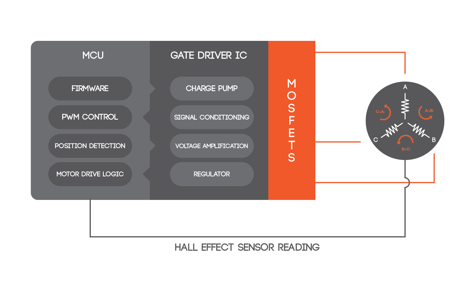
    A Typical Automotive Motor Control System with a 3-phase BLDC Motor

How a Motor Control System Works?

The signal to start or stop an electric motor comes from the microcontroller. Unlike a brushed DC motor, where there are brushes to complete the motor circuit, BLDC motors use Hall-effect sensors to energize the motor coils.

The microcontroller uses the input from Hall-effect sensor to determine the position of the rotor. Based on the position, it will energize the motor coils thus creating a rotating electrical field. This field will move the rotor along with it.

This is the physics and mechanics behind the motor movement.

Post this, we discussed the electronics behind the motor control system and the role of MCU and the gate drivers.

The Microcontroller unit is ported with the motor drive logic, Pulse Width Modulation module and other algorithms depending on the application. Based on the logic, the PWM signals will be relayed from the MCU. The Hall-effect sensor will determine the exact moment when the PWM signal should be sent to the motor.

For example, if the BLDC is deployed in an electronic power steering, the MCU will have steering control/assist algorithms and PWM signal will be produced according to that logic. The timing will still be controlled by the Hall-effect sensor.

While the microcontroller unit gives the BLDC motor a start, there are other components required to keep it running. They are the gate driver IC or the MOSFETs. Power control and motor drive are two things that the MOSFETs and gate driver unit are tasked with.

As mentioned earlier, MOSFETs can amplify current and voltage to fairly high levels. However, at times, a gate driver IC is also required to condition the signal going to the MOSFET. The gate driver IC or the pre-driver IC is a kind of pre-amplifier that filters out the noise in the signal before it is fed to the MOSFET and eventually to the BLDC motor.

In most automotive motor control applications, these MOSFETs are structured in an H-bridge configuration where they control the current flow path to the motor coils. This ensures full control of the speed and direction of the BLDC motor.

Now that the working of a motor control system is clear, let’s look at some of their applications in the area of automotive:

Some Common Applications of Motors in Vehicles:

  • Electronic Power Steering-A BLDC motor works with a MCU with steering control algorithm, PWM, current loop PI etc.
  • Seating Control: Electronically adjustable seats are also driven by electric motors. Some advanced algorithms in the motor control system ensure that there is no jerk or sudden start/stop in the seat. It is called soft stop/start.
  • Electric Vehicles Drivetrain: Most electric vehicles deploy an AC induction motor in their drive train. A three-phase AC power input is given to the motor that produces rotating magnetic field. By altering the frequency of the AC power supply, the speed of the wheel can be adjusted.

Concluding Thoughts

The combination of mechanics and electronics has led to various advancements in automotive motor control system. A simple brushless DC motor is now being deployed to make some smart moves as it is driven by motor drive logic.

If you drive a modern car, you must have noticed how smooth the power steering, power window and seat adjustment etc. has become. All this has been possible with advanced motor control system that not only drive a motor in different speeds and directions, but also in an efficient and smooth manner.

However, the most prominent role of electric motors can be witnessed in electric vehicles that are virtually run by motors, both DC and AC. Electric Vehicle pioneers like Tesla etc. are investing heavily on motor control system that can get maximum output from motors with the least input.


  • 0

Embitel Inaugurates Office Operations in Sharjah to Support Accelerated Growth of ME customers

Category : Press

 
Embitel Technologies, a leading Digital Commerce agency, HQ in Bangalore has announced inauguration of new office operations in Sharjah, UAE.

As an Ecommerce solutions partner, Embitel has been successfully collaborating with leading retail brands from the Middle-East.

With business focus and domain expertise in Magento and Hybris platforms, Embitel has been an active partner in accelerating the growth of Ecommerce in the ME region.

With market reports stating that Middle – Eastern Ecommerce market is set to double to $69bn by 2020, there could be no better time than this for Embitel to expand its presence into Middle-east.

“Ecommerce market has shown a remarkable growth in Middle East in the past. Embitel has also been a part of this growth story by collaborating with prominent business organizations to extend our Ecommerce capabilities.” Said Sharad Bairathi, CEO of Embitel Technologies.

The new office will help Embitel in closely understanding and rapidly responding to the growing demand from the region’s prominent business organizations.  The decision will also help Embitel Technologies in assessing the uniqueness of the Middle-eastern market and deliver optimal E-commerce solutions.

About Embitel

Founded in 2006, Embitel Technologies has been recognized by industry stakeholers for e-commerce expertise; especially in the areas of Omni-channel commerce, Web & Native Mobile App Design & Development, Cloud, IT support and Maintenance.

Embitel’ s unparalleled quality of services and innovative Digital Commerce initiatives has helped it to be a part of renowned Global partner Ecosystems like Magento Solutions Partner, SAP Hybris Partner, PIMCORE Solutions Partner, APN Consulting Partner.

ME Office Address:

EMBITEL TECHNOLOGIES (INDIA) PRIVATE LIMITED
Sharjah Media City,
Sharjah, UAE