×

Happy to Help!

This website doesn't store cookies. Enjoy the experience, without worrying about your data!

Great, thanks!

Monthly Archives: March 2019

  • 0

[Vlog – ISO 26262 Standard for Functional Safety] How to Evaluate Hardware Architecture Metrics Using FMEDA Method

Category : Embedded Blog

Functional safety of automotive component directly impacts the safety of the “lives on the road”.

Hence, all the stakeholders of the Automotive Industry (OEMs’, Suppliers, Product Engineering Services Companies) always implement the ISO 26262 Standard for Functional Safety, in letter and spirit..

As per the ISO 26262 Standard, the functional safety of all the E/E components (both hardware and software) need to comply with the appropriate ASIL (Automotive Safety and Integrity Level).

In this video, we have thrown some light on the functional safety recommendations, of the ISO 26262 standard, w.r.t the hardware components of the automobile.

One of the critical action-items while designing a hardware, which is fail-safe, is to derive certain hardware architecture metrics. Some of these metrics are SPFM, LFM, and PMHF.

The focus of our video is FMEDA, an industry-wide accepted and highly efficient method to derive these metrics.

What Topics Does The FMEDA Video Cover:

  • Introduction to the hardware architecture metrics (SPFM, LFM, and PMHF)
  • The need for derivation of these metrics w.r.t functional safety
  • What is FMEDA and how does this method help in derivation of the hardware metrics?
  • Input and Output of the FMEDA method

Finding the “failure modes” in automotive ECU hardware and achieving required “safe state” is critical to the functional safety. The FMEDA video has been designed to help you understand this journey from FMEDA’s perspective.

We recommend this video to embedded automotive engineers, automotive project managers as well as the business managers. We are hopeful that everyone will learn something from it.


  • 0

Understanding What is a Flash Bootloader and the Nuances of an Automotive ECU Re-programming

Category : Embedded Blog

Every Electronic Control Unit (ECU) in an automobile is tasked with executing a specific application. An Anti-Lock Braking System ECU, for instance, ensures that brakes don’t get locked during braking.

How this works? – the ABS software application ported into  the ECU hardware, is able to fetch the vehicle speed as an input and is designed to reduce the brake on the wheels, based on this input.

What role does a Flash Bootloader software play in all this? You may ask!

Well, as the names suggests, Bootloader is the software algorithm that is executed during the booting of the system.

Let’s delve deeper to understand why an Automotive ECU/Control Unit, should have software re-programming capability.

Automotive ECUs (Control Units) support host of functionalities. These features and functionalities have grown to become more advanced and complex.

It has become imperative for the Automotive OEMs’ and Suppliers to ensure that these software-driven control units are always operating in a secure & efficient environment.

This can be ensured only if the ECUs’ (control units), within your vehicle, have the latest and updated version of the software and security patches.

Hence, the application software designed and ported on the MCU platform needs to be updated quite frequently, either through a remote location or at the service station.

The Bootloader software, which occupies the ROM of the Electronic Control Unit, has been entrusted with this responsibility of facilitating the ECU software update.

The following software architecture of a Bootloader Software will help you understand better,

uds-bootloader

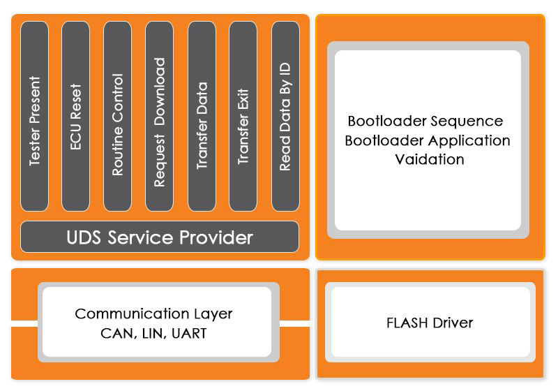
How Bootloader Software Makes Re-programming of an Automotive ECU, an Efficient Process?

An F-35 fighter aircraft has approximately 5.7 million lines of code and a Boeing 787 stands at a little higher than 6.5 million lines of code.

But when on examining a luxury car, one would observe that it has close to 100 million lines of software code.

Thus, the firmware update of an Automotive ECU (Electronic Control Unit) becomes a tedious job, due to such huge volumes of software code.

A Bootloader Software is designed to automate this process of flash re-programming and managing the firmware update.

At every Boot-up of the System, the Bootloader software checks if the latest/updated version of the ECU software is available.

If yes, then before the booting of the system, Bootloader software downloads and stores the new updated version of the firmware. Post this the system boot-up is executed and system now runs on the new version of the software in a completely secure environment.

Understanding how Firmware is Updated, using a Flash Bootloader: a Step-by-Step Process Guide

A Flash Bootloader module is designed to update the firmware without the use of any specialized hardware such as JTAG.

Following is the flowchart of the steps involved in ECU reprogramming using Flash Bootloader:

  • The Flash Bootloader module is the first software module that gets activated during the booting of the system (after the power supply of the device is switched on).
  • The control is transferred to the Flash Bootloader, which checks for the updated version of the firmware. If a new version is available, Flash Bootloader analyzes the update to authenticate the source and cross-check all the pre-defined system security parameters. If the authentication is successful then Bootloader Module writes the new updated on the flash memory, at the target address.
  • Next, the updated program is again verified to check the integrity and fidelity of the software .If no anomaly is found, the control is transferred from the Flash Bootloader to the Application.

All these steps, involved in the process of an ECU reprogramming, are performed by two different parts of the Bootloader- the Primary and the Secondary Bootloader.

In the next section, we explain both of them.

Primary Bootloader: Microcontroller Unit Setup

After the microcontroller is reset, the control first comes to Primary Bootloader. This is the part of the Bootloader software that initializes and sets up the MCU resources.

In the context of a CAN based Bootloader, the resources include the CAN protocol and the CAN controller. The CAN controller is initiated to download the update, with the correct CAN speed.

Any update transmitted over CAN BUS is identified by the CAN protocol and subsequent actions are taken.

Secondary Bootloader: Microcontroller Reprogramming

Similar to the primary Bootloader that initializes various functionalities, there is another part of the Bootloader software that gets active upon receiving the firmware update via the communication medium. It is known as the Secondary Bootloader.

Essentially, this secondary Bootloader downloads the updated related to the target application and reprograms the flash memory.

It has all the necessary flash routines and the UDS functions (if the Bootloader is UDS based) that are necessary for storing the updated data on the flash memory.

The Primary Bootloader transfers the control to the Secondary Bootloader, once the application update is received.

Next, the secondary Bootloader initializes Flash Bus Interface Unit (FBUI) on the RAM memory. This enables the capability to read/write on the flash memory.

Immediately after this step, the communication over CAN is initialized again, so that the Bootloader is ready to receive the UDS request.

Post this, the update is stored in the flash memory. This is when the Secondary Bootloader is erased from the RAM and control once again goes to the Primary Bootloader.

Role of UDS Software Stack in an Automotive ECU Reprogramming

According to the AUTOSAR Standard, Unified Diagnostics Services (UDS) is the most suitable protocol for implementing Bootloader, for the purpose of ECU reprogramming.

There are multiple reasons for that and we would discuss them in detail in other UDS blogs. For now, we will focus on the role played by UDS in a Bootloader operation.

Following are the key responsibilities of UDS in an ECU flashing operation:

  1. UDS sets the server into a reprogramming mode and start the reprogramming sequence
  2. It handles the initiation and termination of the data transfer
  3. UDS takes care of size and order of data blocks to be sent/received and memory blocks where the data will be stored
  4. The UDS services allow the client to start or stop a routine, which may be running on the server
  5. It allows the client to initiate a software reset event on the server

UDS performs all these responsibilities with the help of certain software services. Some of these services and their use in flashing in explained in the table below.

How Remote ECU Flashing works, using a Specialized Flash Bootloader

In order to perform automotive control unit reprogramming, the vehicle has to be brought to the garage where the service engineer will do the needful.

However, as the software used in vehicles is growing in the volume and complexity, numbers of the software upgrades have also become more frequent.

In such scenarios, the OEMs cannot expect the vehicle owners to bring their car to the garage frequently, for the ECU flashing. A Bootloader software enabled with remote update capabilities over Ethernet is the key here.

With DoIP (Diagnostics over Internet Protocol), remote ECU update has become possible. While the rest of the components and services are similar, usage of Ethernet as the medium for communication, has made the remote update possible.

In simple terms, the firmware update that is transmitted over CAN, is sent over Ethernet using a DoIP software stack.

The DoIP stack inside the Bootloader software identifies the message and the entire process of ECU reprogramming is performed.

Whether based on DoIP or UDS, Flash Bootloader is a component that is indispensable, given the importance of regular ECU updates.

And with the remote ECU update capabilities, it is going to be easy for the OEMs and other automotive suppliers to ensure the robustness and safety of the software-driven Electronic Control Units (ECU) in our vehicles.


  • 0

[Video] How a Transition to Model Based Development can Save your Product Engineering Teams from Manual Coding Syndrome

Category : Embedded Blog

Are you aware that manual coding may be costing additional time & efforts of your Embedded Product Engineering Developers?

And not just that, it may also be making your code more prone to errors leading to increasie in time-to-market of your automotive product development projects.

Does all this is making you feel that your teams should ditch manual coding?

Then what is the alternative, you ask? Please meet Model Based Development (MBD), a product development approach, which is the necessary paradigm shift that your business deserves.

Getting curious? Well, we will now stop talking and let our video on Model Based Development (MBD) take over.

The Video covers the following essential aspects of model based designing and development:

  • Why move to Model Based Development?
  • What is Model Based Development?
  • Value-adds of MBD
  • Some possible downsides of MBD

This short video on model based development has been designed specifically for automotive engineering teams of Suppliers and OEMs, who wish to shift to MBD but have some reservations.

However, business managers and other stakeholders in automotive industry can also benefit greatly from this video.

This is the first part of the video series on Model Based Design approach. We will back with videos showcasing a more detailed view of this paradigm.


  • 0

Adobe Symposium 2019

Category : Uncategorized

Watch out for an Integrated Avatar of Adobe Experience Manager and Magento Commerce Cloud

Adobe Symposium 2019

As a digital marketer or an Ecommerce Technology Expert, you can very well relate with the significance of making every “Customer Experience Shoppable”!

But are you still trying to figure out how to best leverage the power of the Digital Trio: Data, Context and Creativity?

We understand your challenges and hence we have penned down these four lines, just for you:

Creativity is Not a Stand-alone Magic Wand,
It should always be in-sync with the ‘Customer Data’ in hand
And if you are also able to decode the Context,
This Trio will ensure that you always deliver a Seamless CX.

This April, meet our Ecommerce Leaders to find out how Adobe Experience Manager and Magento Commerce Cloud can help you overcome your challenges.

16th April , 2019
Grand Hyatt, Mumbai

Please fill the form & Get Your copy of the Event Brochure

Name *

Email *

Company Name *

Phone Number

Meet our Ecommerce Leaders:

Arun Kumar

Business Head- E-Commerce
Embitel Technologies

Anish Bhan

Head of Sales-E-Commerce
Embitel Technologies

Manish Narayan

Technical Manager- E-Commerce
Embitel Technologies


  • 0

[Video Blog] How Does a Vehicle Telematics Solution Work?

Category : Embedded Blog

The first manifestation of a Vehicle Telematics Solution (as a Vehicle Tracking System) can be traced back to as early as 1990s. This was the time when the technologies related to GPS and Vehicle Connectivity to Internet were making waves.

Back then, a vehicle tracking system consisted of a hardware platform, integrated inside the vehicle with connectivity modules. This enabled a communication channel between the Hardware Platform and the local server. All the data in the server was via locally-installed software.

Fast forward to 2019, the modern-day vehicle telematics solutions enable the users to monitor the driver behavior using mobile or web app , receive real-time Traffic alerts, e-call during crisis, track stolen vehicles , send/receive lane change warning,  receive alerts related to the battery health, and more.

Going by the current market trends, it is anticipated that by 2025 the U.S roads would have about 116 million connected cars. And each of these connected cars would be uploading 25 gigabytes of data to the cloud in an hour.

These numbers give us the hint regarding the scale at which the future Vehicle Telematics solutions would be expected to operate.

But the curious mind of an Automotive Engineer would be more concerned regarding the following questions:

  • How is the vehicle data transmitted effectively to outside world through cloud server?
  • What is the technology framework of an efficient vehicle telematics solution that enables reliable car-to-cloud communication?

Watch this Video to Nurse Your Curiosity!

What will You Learn in this Video:

This video will give key insights into:

  • The 3 core technology components of a Vehicle Telematics Solution
  • What role does each of the 3 technology components play within a telematics system?
  • How does the Data Flow within the Telematics System?

Hope you find the video interesting. If you would like to read a more detailed explanation, please check out this blog on vehicle telematics solution.


  • 0

What is CAN Protocol Stack? And Why it is a Critical Software Solution for ECU Communication?

Category : Embedded Blog

As an Automotive Software or Hardware Engineer, in this era of Cars with Connectivity, Infotainment, Smart Features, you already have a first-hand experience of what drives an automobile (beyond the engine and the four wheels).

As automotive enthusiasts and one of the stakeholders of this industry, we all have interacted with the complex network of Electronic Control Units (ECU), who make the modern-day vehicles, a powerhouse of smart features.

Automotive ECU is the component, designed by burning millions of lines of software codes into a hardware platform, that supports features to make the vehicle more fuel-efficient, smart, and functionally safe for the drivers and passengers.

A gamut of such automotive control units, such as ABS (Anti-braking System), Telematics, Transmission Control, Battery management systems and more, work in tandem to give end-users a great driving experience.

This communication is made possible by a robust in-vehicle networking.

Such coherent coordination between the various Automotive ECUs’ is made possible by the software modules that ensure a seamless inter-ECU communication.

And that brings us to the CAN protocol and everything associated with it. Sit tight as we explore the CAN stack and its layered technology architecture.

But first, let’s start with why a need was felt for such a software protocol solution.

Why Automotive Industry needs a CAN Software Stack?

The various control units in an automotive, are part of a closed loop network, designed inside a car. In this system or network, it is imperative for all the ECUs’ to communicate with each other and take necessary actions.

For instance, a spark from the ignition system fires up the combustion chamber. For optimum power and fuel-efficiency, the time at which the ignition is initiated, by this closed loop system, is very critical.

To achieve this, the ignition system communicates with the engine control unit with the help of in-vehicle networking. This is exact time ignition initiation is calculated.

A more complex system that showcases the importance of communication between the control units is Transmission Control Module, in automatic cars.

The Transmission Control Unit changes the gear ratio with the changing speed. To ensure smooth gear shifts, information from Engine Control Unit and various other nodes are collected and processed.

While the need of communication is well established now. But to develop a deeper perspective, let’s take a stroll down the lanes of the history.

In the early 70’s when electronics system had surpassed the nascent stage of development, it started leaving an impact on the automotive industry as well.

The electronic devices inside a vehicle rose in number and their correlation also got complex. The different control units had communication signals to send to each other and point-to-point wiring was making the system clogged and hard to manage.

Moreover, the information exchange between the automotive ECUs had to be in real-time. All this led to the release of CAN bus system in 1986.

CAN with attributes like faster data transfer, low cost, error diagnosis and more, was the ideal bus system that the control units required. The limitations of adding new features to the vehicle that emanated from complex dedicated wiring was mitigated by CAN protocol.

Delving Deeper into CAN Protocol Stack and its Layered Architecture

CAN protocol (as defined by ISO11898), is a well-defined framework, based on which all the Automotive OEMS’s and Suppliers design communication interface between the various control units. .

CAN Protocol defines, how the vehicle data like engine speed, vehicle speed, diagnostics information etc. should be shared between the ECUs.

Every control unit (known as a node of the network) that needs to communicate using CAN protocol is connected via a Serial BUS.

To enable the transmission and receiving of the data, there are certain hardware and software components embedded in these nodes.

Typically, for a CAN node to be able to transmit and receive messages, it needs to have following components:

  • Host Controller (MCU): Host controller is the Microcontroller Unit, which is integrated in the system in order to manage the execution of the functions and features of a specific Automotive Control Unit/ECU. For example, a Battery Management System (A control unit) is integrated to manage a specific task of monitoring the health of the battery in an Electric Vehicle. A Battery Management System (BMS) Microcontroller can request for information from other ECUs and sensors (via CAN), in order to handle this assigned responsibility.
  • CAN Controller and CAN Transceiver: CAN controller is a hardware chip/platform that can be added to the host controller as a separate component or can be embedded inside it. This CAN Controller has the responsibility to convert the messages in accordance with the CAN protocol.

The transceiver then transmits the messages over the CAN network. The CAN transceiver along with some other layers such as ISOTP and Bootloader, together comprise of a CAN Stack.

Understanding CAN Protocol Stack Architecture

CAN protocol is based on the famous ISO- OSI reference model. There are seven layers through which every data packet passes, before it is transmitted or received.

This 7-layered structure is industry-accepted and widely adopted approach used in communication protocols.

The CAN protocol leverages two such lower layers; viz. the Physical and the Data link Layer.

When this protocol is packaged as a stack, few more modules are integrated, in order to make it suitable for the particular microcontroller platform.

Here is a snapshot of the CAN stack architecture to help you understand it better.

CAN stack

CAN Stack Architecture Diagram Showcasing Different Layers and Modules

Let’s talk about each of the modules one at a time.

  1. CAN Drivers (Low Level Drivers): CAN stack has a number of low-level device drivers like MCU, EE Prom. But we will limit our discussion to CAN drivers only.

    The CAN driver enables the access to hardware resources, for the upper software layers.

    It also offers access to the hardware independent API, to the application layer.

    Services for initiating the transmission and callback functions of the CAN IF module are stored in the CAN driver. The CAN driver also consists of software services that manage the behavior and state of the CAN controllers (if they are part of the hardware unit).

    Acceptance Filtering (Hardware Based) of signals and messages is also one of the functions of the CAN Drivers.

  2. CAN Interface (CAN IF) Layer: CAN IF is a critical software module, that helps in the hardware abstraction of the system.

    It is responsible for services like Transmit Request, Controller Mode Control etc. Essentially, it carries out all hardware independent tasks, related to the flow of data to the upper layer modules of the CAN stack.

    In a real-world application, this layer has to be configured based on the CAN matrix file. This file contains information related to all the Tx and Rx messages.

    Conversion of the CAN Matrix file, which is available mostly in the DBC format, can either be carried out manually or by using a tooling solution.

    However, for this conversion, the DBC to Configuration File generator tool is recommended, as it completes the conversion process in a matter of few seconds. Manual method often takes 1-2 weeks depending on the size of the matrix file size.

  3. CAN Network Management: CAN NM, as this module is popularly known, handles the sleep/wake up functionalities. In simpler terms, it coordinates the transition from normal network operation to bus-sleep mode of the network.

    It also detects whether all the nodes in the CAN bus network are ready-to-sleep. In a scenario when no data units are received for a node, for certain pre-defined duration of time, CAN NM initiates the switch to BUS sleep mode. Once, the transmission of data units is restored, CAN NM wakes up the node. This helps in saving the power another resources of the system.

  4. Bootloader Software: Bootloader Module needs no introduction. It is a software module designed for the re-programming of an automotive ECU.

    The Bootloader part of the CAN stack has UDS (ISO 14229) and the ISOTP layer (ISO15765).

  5. ISO TP Layer (ISO15765): ISO Transport Protocol is a specialized protocol that shoulders the responsibility of the data transmission, when the data frames exceed the maximum payload of 8 bytes. ISOTP layer segments the message into multiple data frames and reassembles them in the correct order, by using the metadata.

Conclusion

CAN protocol has stood the test of time and has virtually replaced every other communication protocol used in the automotive industry.

Its robustness and data handling capabilities, has made CAN a widely used protocol in other industries including Railways, Aviation etc.

The inherent error handling capabilities also makes CAN, a protocol of choice for the majority of the automotive OEMs.


  • 0

[Video Blog] What Makes Pimcore An Ultimate Digital Platform For Enterprises

For the Global Retail Brands, Personalization is the one of the key aspects. When implemented accurately, personalization in product and/or service offerings can help retailers to stay relevant in the super competitive online market.

Personalization, in online commerce, means offering personalized product catalogs and information that is relevant to the prospective customer based on key parameters like his/her geographical location, age, gender, past purchases and more.

But integration of Personalization in Ecommerce  comes with its own set of challenges. Your ecommerce ecosystem needs to be equipped to manage the product information and digital assets that are stored in discrete databases, CRM, and ERP systems.

Challenge is also in handling the sheer amount of customer data, which is aggregated from multiple customer touch points.

In such a scenario, one needs a robust digital solution that supports dynamic product management as well as digital asset management.

Does PIMCORE Platform has such capabilities. Let’s find out!

Watch The Video:

What Will you Learn from this Video?

Watch this video to find out how PIMCORE helps in solving your product information managament vows. You will also learn about :

  • Significance of PDM, MDM & DAM
  • How Pimcore Software proves to be a boon for your ecommerce development projects?
  • Who will Find this Video a Value-Add?

    From Ecommerce Solution developers to business looking to launch their business online  – anyone associated with the world of digital commerce may find this video interesting enough.

    Hope you liked this video blog. Stay tuned to the this space to watch more technology videos and blogs.


    • -

    A Million Dollar Question – Should I Build or Buy the SCADA Solution, for an Enterprise Industrial Automation Project?

    Category : Embedded Blog

    Supervisory control and data acquisition, popularly known as SCADA System, is not a new kid on the block (in the Technology World).

    A SCADA System has been accompanying Industrial Automation Solutions, since time immemorial! It has been playing the role of eyes/ears (data collection), brain (data processing) and tongue (data- insights communication) of an Automation System

    In its latest “IoT Avatar”, the new generation SCADA System is a new beast altogether! SCADA 2.0 (powered by “Internet of Things” Technology Stack) is scalable, possesses more computation power, is cloud connected + mobile UI friendly and hence available anytime-anywhere.

    Industrial SCADA solution

    Industrial SCADA solution. Image Source: orgsync

    Having realized the potential of SCADA Solutions powered by IoT, businesses are ready to decommission the legacy systems and invest in Smart SCADA Solutions.

    However, there is one pertinent dilemma that most of the businesses face, when they kick-start this journey: Should we invest in an off-the-shelf or custom developed SCADA solution?

    In order to help you find some answers, we have put together this blog. All the findings are based on our conversation with IoT consultants, who have a solid domain expertise in Industrial Automation.

    In this blog, we talk about key technical and business factor to consider , while choosing between an off the shelf vs custom developed SCADA.

    Unravelling the Build Vs Buy Puzzle: Analysis of the Key Decision-Making Factors

    Shelf vs Custom
    Image Source: hexacta

    1. Business Considerations:
      • Degree of Freedom/ Ownership:

        When you custom develop the SCADA solution, you can opt to own the IP rights of the complete solution . This provides you the freedom to keep upgrading or fine-tuning the solution, as per your future business needs.

        (In the subsequent section, we also discuss how this helps in Automated Management & Maintenance of your industrial assets)

        On the other hand, the IP rights of an off-the-shelf SCADA solution are in control of your Product Vendor.

        This means for any requirement related to change/upgrade requests, future scalability, quality management ; you are more or less dependent on your SCADA solution vendor.

      • Cost Savings:

        When you invest in Custom Designed SCADA Solutions the Total Cost of Ownership (TCO) depends on the following factors:

        • Per unit cost (including the licensing cost )
        • Number of units, as per the business requirement of your Industrial Automation project.
        • Support and Maintenance Cost


        When you invest in Off-the-Shelf SCADA Solution, i.e, purchase a readily available solution, one can end up incurring higher costs. The following are some practical scenarios:

        • Your business demands inclusion of functionalities, in addition to those provided by the Off-The-Shelf SCADA Solution. You can , in that case, work with your in-house development team to custom develop these features. Other options are to either partner with a Solution Vendor ( by negotiating the additional development cost) or buy an upgraded version.
        • A new upgraded version of your existing Off-The-Shelf SCADA Solution is now available in the market. In this case, your business needs to invest time and efforts in checking if the upgrade will have any impact on the existing Automation System and if any changes are needed in the existing systems/processes.


        To summarize, more often than not, investment in a Custom Developed SCADA solution is a CAPEX (Capital Expenditure). As a business, you invest in a scalable solution that is entirely owned by your organization.
        CAPEX

      • Option To validate your solution design with a PoC:

        In case of a  custom developed SCADA solution, one can take the Proof Of Concept (PoC) Path and conduct a field trial of the prototype.

        After validation of the capability of this SCADA PoC design , one can undertake the full-fledged enterprise production.

        The PoC approach renders additional benefits like early-stage identification of potential mistakes and design flaws. This way, one can take the necessary corrective actions and overcome these challenges in the final custom-designed SCADA System

        Also Read: blog on how PoC accelerates the chances of a successful IoT  implementation

      • Time to Market:

        As a rule of thumb, the time to market associated with custom developed SCADA solution is more than the commercially available solutions. This is mainly due to the hardware and software development cycles.

        On the contrary, an off-the-solution SCADA package supports a faster deployment and hence has a comparatively lesser time-to-market.

        Custom Developed SCADA Off-The-Shelf SCADA Solution
        More flexibility to customize and make changes You have to use the options provided by the Commercial solution vendor
        You own the IP rights of the entire custom developed solution IP rights are with the Solution vendor
        Investment in a Custom Developed SCADA solution is a CAPEX for your business. It can turn out to be more costly, considering that this is a long term investment
        You need the support of teams with in-depth expertise in hardware and software system development, testing and maintenance Support and Maintenance Services contracts can be signed with the SCADA Solution vendor or any 3rd party
        Time to market is high due to the Hardware and software development cycles Lesser time-to-market
    2.  

    3. Technical & Functional Considerations:
      • Creating customized Data Insights That are Actionable: If your industrial automation projects is expected to perform the following tasks:
        • Data Ingestion and processing
        • Interpreting certain conditions as normal ones or as problems
        • Setting alerts based on set parameters


        In that case, a  custom developed SCADA solution is preferable. Why? Here are the top reasons:

        • A SCADA solution tailor-made for your systems allows you to configure necessary data analytics to slice and dice the data, as per your unique business needs.

          Data Slicing and Dicing refers to process of segmenting, grouping viewing and comprehending data within a database. Under these process, large volume of data is repeatedly segmented into smaller portions until the correct level of detail is achieved for proper analysis.

        • A customized SCADA solution offers better scope for integration with advanced Business Intelligence (BI) tools such as QlikView, Tableau etc.

          This enables your organization to have a unique view and analysis of the aggregated SCADA data , and convert them into actionable insights.

          Thus a custom build SCADA solution package enables you to make the most of your enterprise data, beyond the traditional offerings of an off-the-shelf SCADA solution.

      • Automation of  Maintenance and Field Service Workflows:

        When you own a custom developed solution: You have the freedom to automate the maintenance workflow of your industrial equipment, whenever you intend to, with minimal downtime. How?

        • You can define process programs to act as alternatives/aliases when a particular equipment, say the PLC/RTU, is being maintained . This way you can ensure that the maintenance activity doesn’t affect the overall system processes.
        • You can implement custom process programs, unique to your industrial assets, to monitor and service them on time.

          For example, using custom programs an industrial equipment requiring maintenance can be powered to send automated service requests to the specific service vendor, using HTTP-based REST APIs.

        • Additionally, you can leverage custom predictive analytics within the SCADA application to predict impending problems and perform predictive maintenance of your industrial plant.

         
        With an off-the-shelf solution, you are totally dependent on your vendor, who will offer maintenance and service support based on a pre-defined workflows and terms & conditions.

      • Interoperability & Scalability:  Industrial control systems are a heterogeneous mix of devices, communication protocols, and computing devices.

        ‘Build or Buy’- regardless of which SCADA solution strategy you intent to choose, it is necessary to ensure that the final SCADA solution is compatible with:

        • Operating System ( Windows, Linux)
        • Communication Protocols ( Ethernet, Profibus, or proprietary plant communications protocol)
        • Types of Remote Terminal Unit ( RTUs)
        • External devices/Applications from which SCADA can receive or send information/ commands


        An off-the-shelf solution may offer limited options in terms of compatibility with your industrial systems. On the contrary, the technology architecture of a custom developed solution can be designed to support the necessary compatibility with various systems and protocols.

        This way they can also be scaled up to accommodate addition of industrial equipment to be monitored by standardizing the higher level controlling process.

      • Leverage the value-adds of a  Custom Designed HMI: A custom developed HMI gives you more freedom in interacting with and managing your Industrial Assets.

        This is facilitated by features such as multilingual support, Touch and Gesture controls and more.

        With an off-the-shelf SCADA package you may need to integrate external tools, for improved visualization and interaction, that too at an additional cost.

    Concluding Thoughts:

    Thus , performing a cost-benefit analysis of the above mentioned  parameters/ factors might help you easily decide between an off-the-shelf and  custom developed SCADA solutions. The best SCADA solution is the one that easily represents your present and future needs!

    Before making the final choice it is always advisable to create a checklist of functional and business requirements of your industrial SCADA solution. This could include need for remote access, interoperability, deep analysis of the industrial data, or highly customized HMI.

    If the Build vs Buy SCADA dilemma still leaves you puzzled, you may take expert guidance from an experienced  IoT consultant .