In our first video on CAN Bus software stack, we discussed the need for such an in-vehicle networking protocol and how CAN BUS Protocol Software works.
However, the complete understanding of CAN Bus software can be acquired only when you dissect its layered architecture.
For an automotive application to fetch vehicle data or to interact with other applications, a gamut of software modules is required.
CAN BUS Software stack is a bundle of all such modules that make it an invisible hero of the in-vehicle networking (ECU communication).
In this video, we will learn about several of these CAN Bus software modules in brief.
Interested in detailed understanding of the CAN Bus software architecture? Check out our blog https://www.embitel.com/blog/embedded-blog/what-is-can-protocol-stack-why-its-critical-software-solution-for-ecu-communication
Our Latest CAN Bus Protocol Stack Video Will Cover:
Overview of the CAN BUS software architecture
Application Layer of the CAN Bus Protocol Stack
CAN Network Management (NM) Layer and CAN Interface (IF) Layer (CAN Software Stack)
UDS (ISO 14229) Based Flash Bootloader
ISO Transport Protocol (ISO 15765) Layer
CAN Drivers
As CAN Bus software is at the heart of ECU communication, automotive embedded engineers should have its crystal clear understanding. This video is great way to start building this understanding.
Even for the business managers and decision makers, this video will aid in understanding the pain points of their customers.
”From Combustion to Electric” is the latest Wave of Innovation being witnessed by the Automotive Industry. This nudge towards Battery Driven Electric Vehicles is not only from within the industry but also from the governments
For example, “Made in China 2025” is an ambitious and aggressive initiative from Chinese government to ensure that country enjoys the highest share of Electric Vehicle production in the global market.
However, the widespread acceptance of Electric Vehicles will depend on the efficiency of the Electric Car or Electric Scooters. And that partially boils down to the Motor Control Solutions that powers the EV drivetrain.
A motor control solutions is lot more than merely a system that controls the driving speed of Brushless DC Motor or a PMSM motor. A number of algorithms are at play that ensure smoother driving experience, ECU diagnostics, efficiency and more. Furthermore, in order to drive motors of different capacity, using the same motor controller, additional power control mechanisms are required.
Working on these lines, Motor Control system experts at Embitel have built an Electronic Control Unit (ECU) Platform , which is capable of driving PMSM and BLDC motors of different capacities.
This Control Unit Development Platform for motors, can help you unlock the true potential of your innovations in Electric Scooters, E-Auto, Electric Pick-up Trucks, Electric Four Wheelers and more. This one-of-a-kind motor control system has a host of features including the coveted Field-Oriented Control (FOC)algorithm.
Let’s take you on a walk-through of our Motor Control ECU architecture, which is also powering the Electric vehicle initiatives of one of the leading Indian OEM.
[Demo Video] How FOC Algorithm Works in A Motor Control Solution for Electric Vehicles
The All New Motor Control System ECU from the Innovation Labs at Embitel
Innovation has been the in the DNA of Embitel from its very beginning. And to ensure that it doesn’t just remain a word uttered occasionally in seminars and monthly mailers; we have set up an Innovation lab. Mr. Sitaram heads this R&D Lab as the Chief Innovation Officer. The ideas from all quarters are welcomed and nurtured by this incubator and R&D Team.
One of such ideas to develop a ready-to-deploy motor control system was incubated in the lab and which has now transformed in a cutting-edge solution offering for our customer.
Let’s now get started to learn all about our in-house designed and developed Motor Control Solution ECU (Welcome to “Make in Embitel” Zone)!
How our EV Motor Controller Unit Design Helps to Overcome a Critical Pain-Point of the EV Industry
The push towards electric vehicles is not limited to cars and 2 wheelers only. To ease the load on Diesel driven public transport vehicles, E-Autos, E-Rikshaws and other such vehicles are being promoted. However, there are certain roadblocks that need to be overcome, w.r.t the application of electric motors in EV.
While Brushless DC and PMSM motors have been the preferred electric motors for electric vehicles, their power requirements differ for different types of EVs.
For better clarity, let’s take an example of an OEM who is working on different segments of Electric Vehicles (like 2-wheelers, three-wheelers, 4-wheelers and even electric commercial vehicles).
Each vehicle will require an Electric Motor of different power ratings and hence a separate motor control solutions needs to be developed for each of them. Increased time-to-market and inflated cost are two of the adverse effects that this OEM will need to overcome.
This challenge (related to Motors of different Power Ratings) can be overcome with our EV Motor Controller Unit. Its two-tier technology architecture is designed to separately manage the Power Control and drive algorithms (that drive the motor). Simply put, the microcontrollerdriving the motor will remain unchanged for every motor (BLDC or PMSM).
Only a separate hardware chip, called the daughter board will need to be customized based on electric motor’s power rating.
Need more clarity? The layered Software and Hardware architecture will help you develop a better understanding!
Understanding the Layered Architecture of EV Motor Control System ECU
Before we look at the architecture of the EV Motor Controller, let’s explore the components of the Control unit.
Microcontroller Board: MCU board is the main controlling unit. We call it so, because the Field-Oriented Control algorithm and the vehicle diagnostics stacks are embedded in this MCU. In addition to these algorithms and software stacks, the HAL (Hardware Abstraction Layer) and Low-level Drivers (LLD) are also part of this board.
Daughter Board: This is the hardware component which manages the power delivered to the Electric Motor. It is small board designed (and can be customized) to drive a BLDC or a PMSM motor of specific Power Rating.
This ensures that the same motor control system can drive different electric motors, by merely customizing the daughter board for specific Power Ratings. It essentially has the MOSFETS that receives the Pulse Width Modulation (PWM) signal from the MCU board and redirects it to the motor as per its power rating.
In this way, our Motor Control System is designed to deliver a more cost-effective solution for Electric Vehicle OEMs.
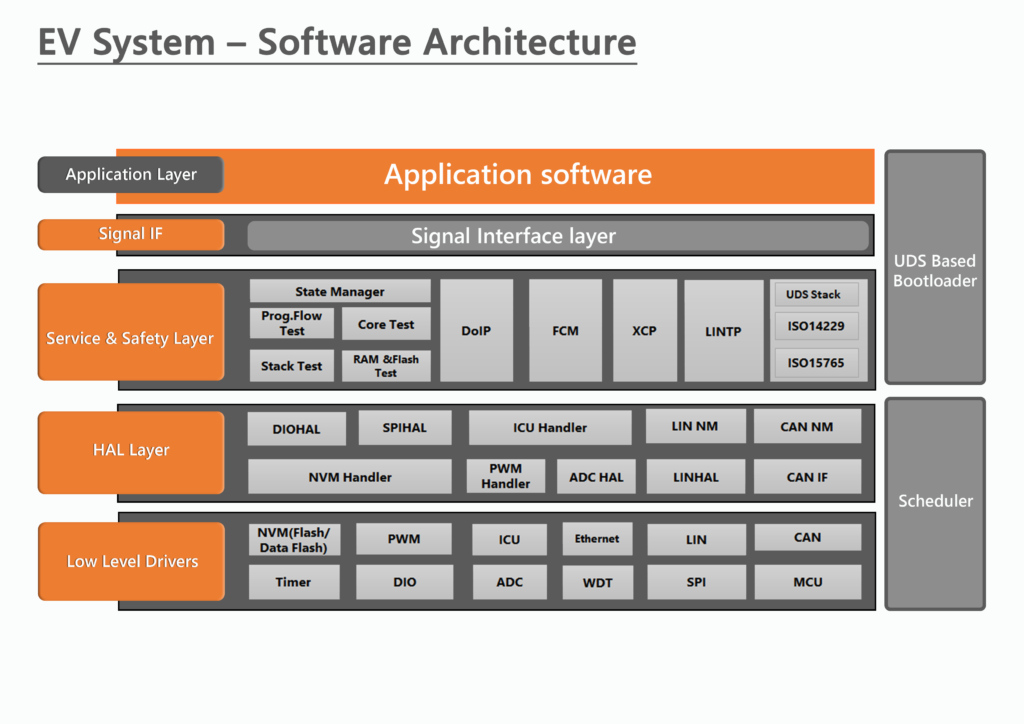
Now let’s understand the software architecture of our EV Motor Control System.
Interface Layer: The role of the IF layer is to act as an interface or a bridge between the application layer and the other layers of the motor controller platform. The Application Layer (not part of our platform) will host all the OEM-specific applications. .
Service, Safety and Utility Layers: These are the most important layers in terms of functionality. The coveted Field-Oriented Control algorithm is part of these layers, along with other safety, in-vehicle networking and vehicle diagnostics stacks.
Now let’s have a more detailed overview of the software architecture:
FOC Algorithm: Field-Oriented Control is a vector control for electric motors. The torque produced using a scalar control method creates oscillations, thus impacting the efficiency adversely. FOC algorithm, with the help of mathematical calculations (facilitated by the microcontroller), can maximize the efficiency of the electric motors such as PMSM motor or a Brushless DC Motor.FOC does this by decoupling the torque and the electromagnetic flux generated by the motor. When this decoupling is achieved, the torque can be controlled independently without interfering with the electromagnetic flux.
Also, using FOC algorithm, PMSM and Brushless Motors can be operated smoothly over a wide range of speeds. Looking at it from an EV perspective, FOC is capable of driving an electric motor to generate quick acceleration and deceleration.
UDS Stack (ISO 14229): UDS software is included for Off-board diagnostics. The diagnostics trouble codes when captured are stored in the EEPROM to be retrieved later in the garage.
Other modules like LINTP, XCP, FCM, Stack Test, CPU Load etc. are also included for safety, in-vehicle communication and fault handling.
Hardware Abstraction Layer: HAL comprises of the routines and functions that lets the upper layers interact with the ECU hardware. As seen in the diagram, CAN Network Management, CAN Interface, LIN Network Management, ADC etc. are some of the protocols for which HAL has been included.
The Hardware Abstraction Layer in this motor control system comes in handy when the algorithms need to be migrated to a different MCU family.
Low-Level Drivers: LLDs is the basic microcontroller peripheral. It has no idea about the nature of the value that it is receiving from the microcontroller. Its job is to pass on the value to the HAL where the value will be converted to a physical value.
For example, the LLD measures a current value which is 0-5 V. When this value is received by Hardware Abstraction Layer, it is converted to a physical value of 0-30 A. LLDs for PWM, ADC, LIN, CAN and MCU are included in the bottom-most layer of our EV motor control system.
The hardware platform that supports our FOC algorithm and other software stacks is also a very crucial part of the EV motor control unit. Let’s have a quick overview of the underlying hardware.
Hardware Architecture Powering Our EV Motor Control System ECU
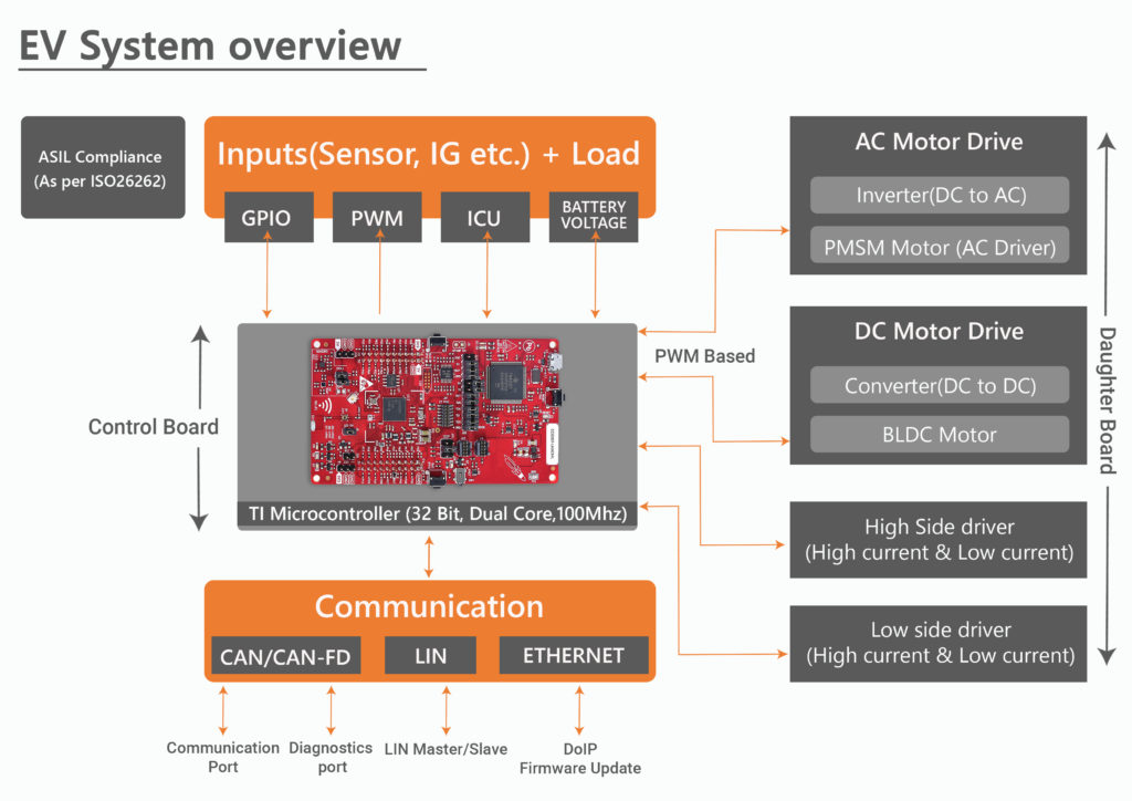
Our EV Motor Control Unit has been designed on an Automotive-grade,Dual Core Microcontroller platform– 32 Bit TI Delfino.
The Control Board (Microcontroller) receives inputs from:
Vehicle Sensors: Including the throttle sensors, brake sensors, Torque sensors over an Analog channel. Data received from these sensors are fed into the FOC algorithm for mathematical computation of PWM signal. This signal drives the electric motors.
LIN, CAN and UART Transceivers: Messages from other ECUs are received through CAN, LIN or UART protocols. The respective transceivers act as an interface between the in-vehicle networking protocols and the physical medium (CAN BUS/LIN Bus/RS 232)
OBDII CAN: OBDII protocol also communicates with the microcontroller board for emission related data.
This EV System overview will give a better understanding.
Based on these inputs, the Field-Oriented Control algorithm directs the MCU to generate PWM signals. These signals are sent to the Daughter Board (Power Board).
Daughter Board, as explained earlier, is the power management system of our EV Motor Controller unit. Also called as the power board, it is responsible for generating the current supplied to the electric motors. As mentioned earlier, it consists of varying number of MOSFETS for this purpose.
The addition of the Daughter Board has made our motor controller platform a highly flexible and a universal solution for Electric Vehicle Applications. Whether you need to drive a smaller BLDC or PMSM motor or a bigger one, the MCU remains the same. All one needs to customize is the small daughter board
Customizations Required to Cater Different Use-Cases of EV Motor Control Unit
The customizations for different use-cases essentially boils down to
the number of MOSFETS
the power capacity of the MOSFETs. (that are integrated with the Daughter Board
Higher the power rating of the motor, larger the number and rating of the MOSFETs. For instance, our prototype motor control system designed for a 5 KW BLDC motor has 6 MOSFETs in parallel on each side of the board.
Now to drive a smaller EV, say an electric 2-Wheeler that requires a 1 Kw motor, the daughter board will require only 2 smaller MOSFETs. Other supporting hardware components will also be based on the electric motor’s power rating. Final Remarks
As quite evident from its design, our EV motor control system ECU is designed to cater to the changing needs of the Electric Vehicle industry. The segregation of motor drive logic (FOC algorithm) and power management aids in faster turn-around time of EVs. For a Demo of our Motor Control system for Electric Vehicles, please contact us at sales[at]embitel[dot]com.
Internet of Things (IoT) has made Automation, Monitoring, Reporting, and Connectivity processes smarter and more efficient.
Are you a History Buff? Then the Story of Evolution of IoT Technology is a must read for you! Read the entire blog here : Unraveling the Story of Evolution of IoT and Its Rapid Adoption
Due to these virtues, IoT has witnessed widespread adoption across industries like logistics and inventory management, industrial automation and Connected Cars (to name a few).
The global internet of things (IoT) market is anticipated to reach USD 724.2 Billion by year 2023, as per the report by Research Nester titled” Global Internet of Things (IoT) Market Outlook 2023 “
This indicates the volume of trust, confidence and expectations businesses have in the Internet of Things Technology Stack.
When the Stakes are High, the Responsibilities shouldered by the IoT Design and Development teams become More Critical.
Thus we thought that it will be interesting to explore this Universe of IoT from a software/hardware developer’s perspective. In this context, “Forewarned is Forearmed” perfectly sums up the best way forward for an IoT Engineer.
Being aware of the possible IoT Design Mistakes is akin to Half the Battle Won. Hence, we worked with our IoT Consultants to list down the possible design and development mistakes. Watch this Video to know more!
Video to be embedded here
What to Expect in this Video:
The vlog will walk you through a few must-avoid design mistakes. Following are some design aspects that we have taken into account, while designing this video:
System Security
Operating Environment of IoT Field Devices
Personality of Software Codes Created
Data reliability
IoT testing Practices
Regulatory Compliance Process
Hope you will find this video useful.
Please click on the subscribe button above to receive notifications about our latest blogs. Feel free to share these blogs through your social media handles, by clicking on the icons given below!
Any discussion around the connected car ecosystem is incomplete without the mention of Automotive infotainment systems. What used to be a luxury addition is slowly starting to become a must-have feature in cars of different segments.
This is because, Automotive Infotainment systems – are helping the OEMs in realizing their vision of delivering a personalized, connected and safer experience to the end-consumers.
It won’t be an exaggeration to state that the Automotive World is moving towards the era of Digital Cockpits in Cars!
Also read our blog: A Car with a Cockpit: How Digital Cockpit Solutions are Making This a Reality
In this context, the importance of developing a reliable, secure and robust automotive infotainment system cannot be emphasized enough.
This calls for a fool-proof testing process that can validate the automotive infotainment system against any probable functional, operational and usability failure. This blog is a summary of our conversation with our in-house technology and testing experts to understand the different software and hardware testing practices that are followed during automotive infotainment solution development.
First Impression is the Last Impression: Ask an Engineer Testing UI of an Infotainment System
GUI (Graphical User Interface) , is one of the most important components of an automotive Infotainment System, for embedded software testing teams.
An intuitive GUI is very critical. It dictates how pleasant an end-user’s interaction with your product will be!
Every product development team knows the fact that all the information should be clearly and concisely displayed within the designated space, in a user-friendly and attractive manner; but achieving this is often not easy.
During the infotainment testing phase, the UI of the automotive infotainment system is checked for important parameters such as:
Screen text and characters
Font and Formatting styles,
Widgets/icons and their attributed behavior
Screen coverage
Alignment of images and characters
Image clarity and screen resolution
Image 1: In-vehicle infotainment System
When it comes to UI testing of an infotainment system, two primary approaches are followed:
Manual Testing – Under Manual Testing, as the name suggests, manual checks are performed to check whether the specified UI parameters of automotive infotainment system, and other specifications conform to the requirements given by the customer (mentioned in design document and SRS document).
Automated Testing – Under this approach, automation tools like GIMP are used to perform similarity checks and report/log the test results.
When Automation in Infotainment Testing Becomes your Friend in Need!
While it is very thorough, manual testing can sometimes prove to be extremely cumbersome and time-taking.
Hence, there are occasions when one should opt for automation in your infotainment testing process. This helps to make testing activities more efficient and error-free.
So, instead of testing the sync between the vehicle and infotainment system manually, real-time environment can be emulated and tested with specific automated tools and scripts.
A sweeping testing trend these days is to design scripts to run testing complex functionalities without the need of any human intervention (welcome to Automation Frameworks in Testing).
These test scripts are mostly written in programming languages like Python. To make things a bit more clear, let us consider an example. To test the Bluetooth connectivity of the In-vehicle infotainment system (IVI), a software tester will need to connect and disconnect a phone/Bluetooth enabled device several times.
Doing it the manual way would be quite time consuming. So an easy work-around here would be to emulate the actual device (infotainment) environment and test the Bluetooth functionality by running automated test scripts.
But before you get started with the infotainment testing procedure, it is very important to ensure that test environment is stable enough to endure the procedure.
For example, if you need to test if your infotainment system is able to detect and transfer data to a nearby Bluetooth enabled device, you must first ensure that the Bluetooth capability itself is working.
In the context of smart testing practices, that saves up considerable development time, one cannot ignore discussing about the Agile testing, used widely in embedded software development.
What Does Agile Testing Approach Entail?
The Agile Testing Method follows an iterative/continuous workflow rather than a sequential one.
The product under development is continually tested at different stages so that it is as closely aligned to customer requirements as possible.
The Agile Testing approach has several advantages like flexibility and adaptability. It also lets the development team receive regular feedback from the testing team. These feedbacks can be used to further shape the product better.
The agile testing lifecycle consists of the following phases:
Impact Assessment – Involves gathering inputs from various stake holders and users. This acts as a feedback and guideline for next deployment cycle
Planning – Involves planning of the schedule of testing process, meeting frequency, and deliverables
Daily Scrums – Involves everyday standup meetings to catch up with the status of the testing and setting the goals for the current day.
Agility Review Meeting – Involves weekly review meetings to review and assess the progress against milestones.
Release Readiness – Involves reviewing the features that have been implemented and if they’re ready to go live.
You should also note that there are several levels of testing performed at each stage of the agile testing approach.
These include Unit Testing, Integration Testing, System Testing, and Acceptance Testing.
Shifting our focus back to Testing the Infotainment Systems; there are some critical aspects of every infotainment solution that should be tested. Let’s find out more in this context.
Key Attributes of an Infotainment System that your Teams Should e Testing
While testing a high-end infotainment system, the development team should ensure that the system is tested for following key attributes:
Does it have a user-friendly Interface ?
How accurate the functionality of the system is, as per the SRS document
Can the Infotainment system deliver information to the driver without distracting him?
How compatible is the Infotainment system with different platforms ( Android, Linux), file systems, secondary devices ( smartphone, SD Cards, USB) etc.
Have you ensured seamless integration between various components and interfaces of IVI system as per the SRS
In addition to the above, your team also should verify the infotainment system against certain critical security parameters, in order to ensure reliability and safety.
Key Security Testing Parameters:
As the number of functionalities and features supported by the Infotainment system increases, so does its vulnerability to security threats.
An automotive infotainment system can be easily hacked to hijack a vehicle and cause major damage to the driver and others.
Thus, these security parameters must be tested before a system is deemed as fit to be sold.
Session Expiry/Session Timeout
This can be best explained through an example. Suppose that a user has logged into the infotainment application (web or mobile) but haven’t executed any action, leaving it idle for a specific time interval.
Ideally, after this specific interval if the user tries to browse on the app, he should get a pop-up indicating that the session has expired. This ensures that only the authorized used can log-in to the system. This helps in securing the infotainment system against unauthorized access when the user leaves it unattended for a specific duration.
Security against URL Manipulation
An ideal web application will always require a user to login to the system using valid credentials to access any website page. Even if someone simply copies the URL of a webpage and copies it on a different browser, he must be redirected to the login page. This prevents hackers or unauthorized users to alter the URL to illegally get access to web pages.
If your development team has not anticipated this scenario, then your infotainment system is highly susceptible to data manipulation –which can harm the brand reputation.
Testing for SQL Injection
Under this approach, testers themselves try to hack the application by giving SQL commands or other credentials, but what needs to be tested is that the system shouldn’t be vulnerable.
So far we have talked about ideal test practices for testing infotainment system followed by your product testing team. But how do you anticipate and define these test cases? Let us find out:
Best Practices to be Followed When Designing Infotainment Test Cases
While testing infotainment systems, the following kinds of test cases should be designed and planned for:
Straight-forward Test cases – Test cases as per the software requirements specification ( SRS).
Ad-hoc test cases – Additional scenarios anticipated and defined by the testers (without referring to the SRS document).
Negative test cases –These define situations under which an application can fail, or an abnormal condition arises. These are generally not part of the SRS and are done by the testers on their end, based on their experience and ability to anticipate scenarios.
Stress Test cases – Under this, the test cases are defined to determine the load capacity of the application. This is to check how much stress or load the infotainment can gracefully handle without crashing.
For example, the test case specifies flooding the infotainment system with concurrent multiple inputs. This can help in checking how the system reacts, what are the other consequences and risks involved in such a scenario.
On part of the testers, they should have a deep understanding of the application architecture, the inherent project requirements – which mean he should be thorough with important specification documents such as SRS and Design Documents. If the testers are confused at any point, they can’t assume things and carry out testing operations. In such a case they can get back to the module owner and clarify the doubts.
The importance of using appropriate/ efficient testing tools at the right time and in the right scenario can go a long way in future-proofing your final application/end product. Following below is a set of testing tools commonly used for infotainment development projects by our in-house test engineers:
TeraTerm
An Open-source terminal emulator program used for emulating and logging data, sessions etc.
PCAN
Used for monitoring CAN serial bus communication
TestLink
A web-based test management tool used for creating test projects, manage and document test cases.
Supports manual as well automated test execution
JIRA
Software for Agile Project Management , test case management and issue tracking.
To Conclude:
Testing isn’t a complimentary process in infotainment system development project; rather it is a mandatory part of it.
No system should be considered fit to be released until it has been thoroughly tested under various test cases.
And if the best practices discussed above are closely followed, organizations can make sure they’re rolling out a product that’s reliable in every sense.
Electronic Control Units (ECU), the mini computers inside your car, need to talk (communicate) among themselves in order to keep the system up and running efficiently.
For instance, the Engine Control Unit exchanges information such as RPM, Engine Temperature etc. to other control units like Transmission Control Unit or Battery Management System.
So how do OEMs ensure that these Automotive ECUs’ from different Suppliers are compatible with each other?
Well, it’s time for our invisible superhero to make its presence felt!
Our very own CAN Bus Protocol, who acts as the back-bone of in-vehicle networking, ensures that the required compatibility is achieved.
CAN Bus protocol utilizes the underlying CAN Bus, as the physical medium, to exchange vehicle data at a faster rate.
In the first part of this video series, we will introduce you to the CAN Bus protocol and how it is an omnipresent, yet an invisible hero inside your vehicle.
The CAN Bus Protocol Stack Introductory Video will also Unravel:
Why was the need for a CAN Bus Software felt?
A Brief History of CAN Bus Protocol
How does CAN Bus Protocol Facilitate in-vehicle networking
Why is CAN Bus Software Solution so important for Automotive Industry
Understanding CAN Bus Protocol opens the door to in-vehicle networking, ECU-reprogramming and a lot of functionalities and protocols related to automotive.
In that context, this video can be quite helpful for various stakeholders such as new automotive engineers, decision makers, business managers and more.
So sit tight and enjoy the video! We have many such amazing videos on our YouTube Channel. Don’t forget to watch them. Do hit the Like and Subscribe button!
A Car Heads-up Display (HUD) is an important component of a Digital Cockpit Solution. Let’s learn about the Hardware Modules that power it?
The automotive industry stakeholders have a long term vision of offering a safer and convenient in-vehicle experience to their customers! And what is helping them turn their desire into a reality?
The answer is Digital Cockpit Solutions!
Digital Cockpit is a unified solution consisting of a Digital Instrument Cluster, Infotainment, Telematics, and Car Head-Up Display .
These automotive systems that had existed in silos, have been unified and thus leading to the emergence of Digital Cockpit Technology (courtesy Automotive ECU Consolidation)!
Learn more about the tech behind Digital Cockpit. Read here : A Car with a Cockpit: How Digital Cockpit Solutions are Making This a Reality
While each of the above mentioned four components of Digital Cockpit Solution help in delivering connected car experience. The Car Heads-up Display leads the pack; especially due to its innate ability to relay critical and contextual vehicle information to driver in a distraction-free manner!
What Exactly is a Car HUD system?
A car HUD system is a Human-Machine Interface that displays Critical, Real-time information, right in front of the driver’s line-of-vision.
The Head Up Display system displays this information on the windshield or a combiner glass , in a way that the driver is not distracted.
Typically, a car HUD can system enables the driver to :
View Turn by turn navigation
Read car speed, RPM, fuel levels
View Warning Alerts
Access Calls/messages without taking out his/her phone
Adjust the Music system settings
The driver can perform these actions through simple hand gestures without having to take his/her attention off the road.
For the car HUD to perform these functions efficiently, there are certain indispensable hardware components, that work behind the scene!
So what are these hardware components? Watch this video to learn.
Watch the Video here
What can you Expect from this Video:
The video offers a brief explanation to following frequently asked queries related to a Car HUD:
What are the different hardware modules that constitute a Car HUD system?
What role does each of these hardware components play in the efficient functioning of a Car HUD system?
Hope you will enjoy watching the video. Please click on the subscribe button below to receive notifications about our latest blogs.
Also, feel free to share these blogs through your social media handles, by clicking on the icons given below!
Our Customer is a leading manufacturer of Medical Weighing Scales and Measuring instruments. They are a world leader with business footprint spread across more than 100 countries.
Business Challenge:
The customer was looking for a robust software solution, that could inherently address existing limitations and enhance the functionality of one of their medical device product lines.
They were confronted with the following challenges:
Support for rollback of a remote firmware (OTA) upgrade was missing.
Though the medical devices were developed for global audience, there was support for only a limited number of global languages
The customer wanted a cost-effective solution to extend the number of languages in which the system content is displayed. This was necessary to enhance the global level usability of their medical devices.
Stringent FDA regulatory requirements: Customer felt the need for expert guidance in embedded software development, as per the FDA standards
Embitel Solution:
After initial brainstorming sessions and technical workshops, the customer found a reliable technology solution partner in Embitel.
Embitel’s embedded software development team, consisting of Firmware developers and test engineers, got on-board. They performed an in-depth analysis of the software architecture of the medical device.
Let us have a quick look at the solution roadmap, which was followed by this team:
Enabling Multi-Language Support: We customised and re-configured the software of the devices, to extend support for multiple languages. We also enabled the end-users, with the feature , to set and see the content, notifications alerts & more, in their preferred language.
Enabling Rollback of Firmware versions: Embitel implemented a solution to enable rollback of any upgradation of firmware image on the field devices through firmware-over-the-air(FOTA).
Configuration & Customization of Admin & Security Settings: We enabled the end-user (with valid credentials), to configure the medical device as per his/her requirements. Earlier, only an admin user could configure the system with a pre-defined universal admin credential.
We also developed a custom login solution, whereby an end-user can create a custom password on switching on the system for the first time. This also facilitated an enhanced security against any unauthorized system access.
Enabling Custom maintenance Schedule for the devices: The devices were programmed for customized maintenance and service schedule. This has enabled the user to set custom service reminders, as per their convenience
New UI (User Interface) for Better CX (Customer Experience): The device UI was given a make-over by designing a new interface for admin support, multi-language support – as per the wireframe shared by the customer.
Quality Check at every stage of the development process: Rigorous Code quality checks were carried out for bug detection. This also helped to check the software against any vulnerability that may have got introduced during the development stage.
Testing : We performed manual and automated testing of the software solution.
Customized development process as per the FDA guidelines: We followed a custom software ( design, development, update) processes, which were strictly verified for FDA compliance. And in order to ensure FDA-compliance, we performed a project impact analysis to evaluate the impact of the proposed changes on the end device.
Embitel Impact:
Our domain knowledge and on-field experience proved to be a value-add.
Our team was able to, identify & implement innovative business logic, for the challenges and requirements specified by the customer.
Of the various motors deployed in automobiles, Brushless DC motor (BLDC) and Permanent Magnet Synchronous Motor (PMSM) have stood the test of time.
Reasons: Both BLDC and PMSM Electric Motors are efficient, robust and cost-effective.
But the most important value-add of BLDC & PMSM motors (over other Electric Motors) is their ability to be controlled electronically.
This feat alone makes these Electric Motors, a popular choice in development of some of the most game-changing automotive systems like electronic power steering, ABS, and Electric Vehicle Drivetrain.
We talked about a lot of similarities here! Are there any differences? Well! there are many inherent ones. Most importantly the electric current that drives BLDC and PMSM motors.
In our latest video on automotive motors and motor controller solutions, we present to you a comparison of BLDC and PMSM motors.
Important Takeaways from our BLDC vs PMSM Motor Video
How BLDC motors work?
How PMSM motors work?
Advantages of BLDC and PMSM motors
Where are BLDC motors present in an automobile
Applications of PMSM motors
This video on automotive motors attempts to drive home the fundamentals of the two most widely used motors in automotive industry.
Watch for this space for more such informative videos on different aspects of automotive systems.