×

Happy to Help!

This website doesn't store cookies. Enjoy the experience, without worrying about your data!

Great, thanks!

Monthly Archives: August 2019

  • 0

How vTest Studio and CANoe Tools Empower the Automation of ECU (Electronic Control Unit) Testing

Category : Embedded Blog

From Low-level Device Drivers and Base Software Modules to the upper layers like Application Layer, modern automotive ECUs can have more than 20 million lines of source code.

Manual Testing of the C code (source code), made sense when automotive electronics was in its nascent stage. During those days, the  source code was limited to a few hundred lines.

Fast forward to the era of connected car, Automation in Source Code  Testing is the only way ahead.

With the help of Automation Testing Tools, software teams are able to deliver more robust quality code along with reduced time-to-market

The word ‘Automation’ is generally related to making a process less time-consuming. However, in case of ‘automation’ in software testing, this switch from manual testing offers some additional value-adds.

We will explore how automation testing tools deliver these value-add. But before that, let’s compare manual testing with automation testing.

Manual Testing v/s Automation Testing: A Snapshot

Manual Testing Automation Testing
May take one week to 15 days to test a software module of an ECU (Electronic Control Unit). Can be completed  in half an hour or 1 hour
Testing multiple signals simultaneously is not possible Multiple signals can be tested simultaneously using routines (part of code that performs some specific task)
Test reports are created manually using excel sheets. Test reports are created automatically
Test-cases are written  manually. Test cases are written using script and can be re-used in other projects as well
Each test case must be run separately, thereby, increasing the time for testing Multiple test cases can run simultaneously on different systems
Batch testing (keeping the test cases in queue for execution) is not possible. Batch testing is possible without any manual interference
Performance testing cannot be done accurately Stress testing, spike testing, load testing can be easily inserted into the test-case script

How to Set-up Automated Testing Environment Using vTest Studio

Implementation of automation in testing, for an automotive electronic control unit (ECU), requires a set of tools (both hardware and software).

Essentially, while testing an ECU, we simulate it inside a test bench that mimics the actual vehicle environment.

The target is to validate all the functionalities of the ECU and its behavior against the given requirements.

The set-up should be such that the simulated environment exactly mimics the actual vehicle environment.

In order to set up such a test bench, the following three important components are required:

  1. vTest Studio– For writing the test cases in CAPL editor
  2. CANoe Testing tool– For executing the test cases
  3. CAN Case VN 1600/10/30- Network interface for CAN, LIN, K-Line, IO , in order to understand and visualize communication between the target ECU and the simulated ECU

The three components mentioned above interact with each other to make the automation testing happen. Let’s now understand how they are setup to build a testing environment.

  1. ECU Pins are connected to the corresponding modules of the CANoe Hardware (CAN Case VN 1600), as per the project requirements. This piece of hardware is connected to the PC
  2. CANoe Tool is loaded with messages and CAN Databases, that are required for data to be transmitted between the ECUs along with the diagnostics services
  3. Using the CANoe tool GUI, the modules to be tested are loaded in the CANoe tool
  4. In the CANoe tool, these modules are configured as per the project requirements
  5. Now, vTest Studio is initiated and CANoe configuration (performed in step 4) is imported into it.
  6. The required environment for testing automation is now setup and vTest Studio is ready to design the relevant test cases.

This is the minimum setup required for the automation of the software testing of an automotive ECU (electronic control unit).

After the test cases are created, they are executed on the target control unit and reports are generated.

Now, let’s deep dive and understand this automation in testing better. Let us now discuss about  the workflow (step-by-step process) involved in automated testing of a vehicle control unit (ECU).

Understanding the Workflow of the Automated Testing of an Electronic Control Unit (ECU):

Step 1: Creation of Test Cases

  • Scripting for test case creation is done in CAPL. It is a programming language very similar to ‘C’. CAPL was created by Vector to test Electronic Control Units using CANoe tool.
  • Let’s say you are required to test three modules of an ECU (electronic control unit);viz; – Functionalities, Specifications and Error Handling. The test cases for these three modules will be designed in CAPL editor. All the test cases can be compiled as a single ‘build’ or multiple ones, depending on the modules to be tested.

Step 2: Execution of the Test Cases in CANoe tool

  • Now, the build with all the test cases will be run on the target ECU using the CANoe tool. CANoe acts a separate ECU that interacts with the target ECU and runs the test cases.
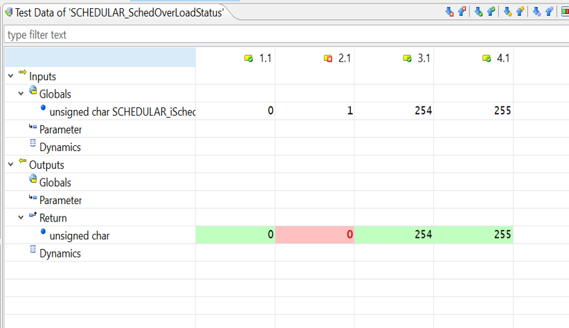
  • The response from the target ECU is displayed on the CANoe tool and test reports are generated.

vTest Studio and CANoe diagram
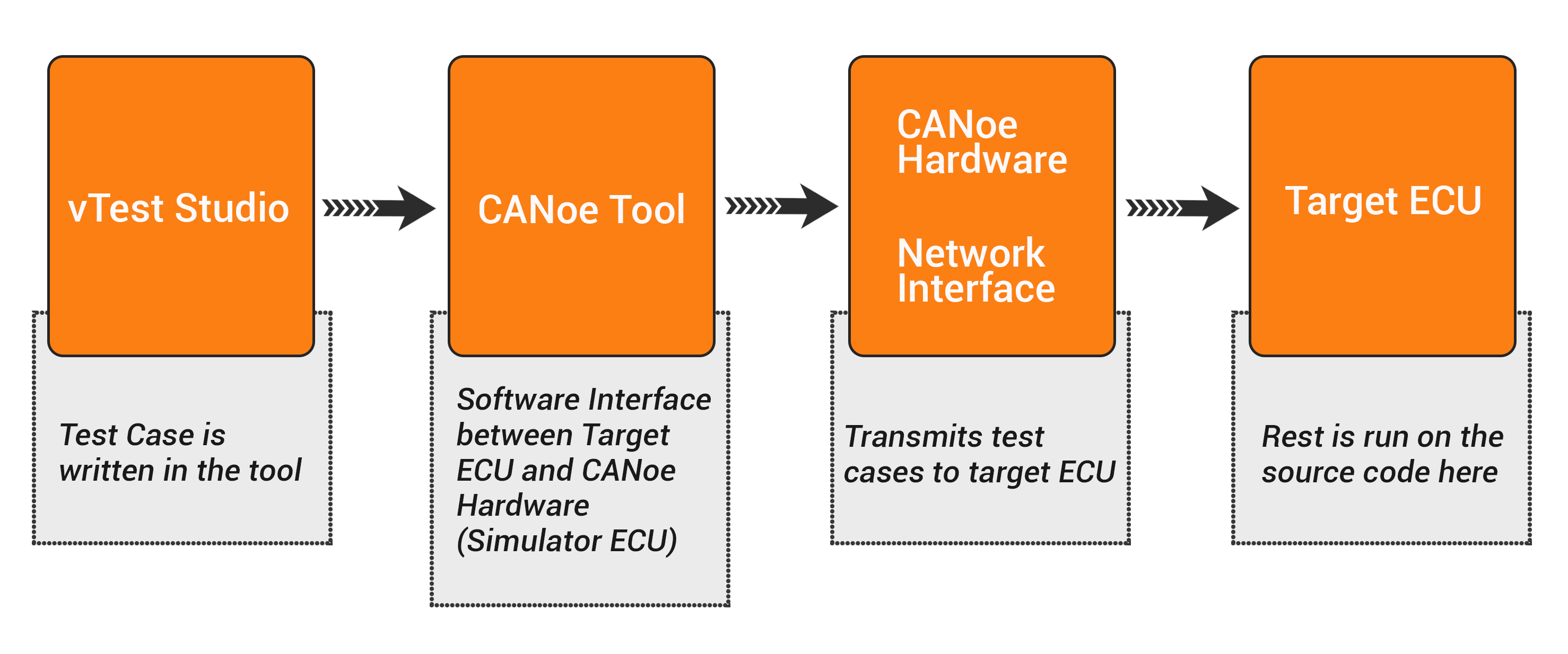
The point to be noted here is, that vTest Studio is used only for creating the test cases. These test cases are run on a separate tool called CANoe.

So, these two tools (vTest Studio and CANoe) complement each other in carrying out automation testing of an electronic control unit.

What are the Value-Adds of Using vTest Studio for Automation of Testing:

  • vTest Studio can cater to a broad range of ECU applications, as this tool is equipped with several test-case editors
  • The test sequences can be given parameters with scalar values, test vectors written in multiple test design languages like CAPL, C# etc.
  • Test projects can be created and maintained in a simple manner using the user-friendly GUI
  • vTest Studio offers universal traceability of the test specifications defined externally
  • This automation testing tool can also provide high test coverage, without the need for writing any complex test case scripts
  • vTest Studio supports Open Interface, this facilitates easy integration with other automation tools = like CANoe.

The Bigger Picture

The cost of implementing automation in testing, especially in case of an Embedded system, is high. However, from a long-term perspective and in terms of ROI, automation in testing is the need of the hour.

What automation testing can do in 1-hour, manual testing may take a week or so. Add to it the human error that might also delay the process and thus, increase the cost.

With automotive applications getting more software-centric, automation testing is the best way forward.

And thanks to automation testing tools like vTest Studio and CANoe, the process gets much simpler and less time-consuming.

All automotive stakeholders like OEMs, suppliers and technology providers benefit from the accuracy and lesser turn-around time made possible by automated testing of automotive ECUs (electronic control units).


  • 0

How MCAL Driver Helps Achieve Hardware Abstraction in AUTOSAR Compliant Software

Category : Embedded Blog

AUTOSAR is a consortium of automotive OEMs and tier-1 suppliers and technology vendors. The objective of this consortium was  to introduce standardization in the development of automotive software.

This standardization begins by hardware abstraction of the applications w.r.t the microcontroller unit (MCU).

AUTOSAR Microcontroller Abstraction Layer (MCAL) is the component responsible for achieving this hardware abstraction. Though MCAL layer (or Hardware Abstraction in general) is part of most  of the software architectures as well, but AUTOSAR MCAL is a specialty software, developed as per the specification of the AUTOSAR Architecture .

Our latest video is the first in the series on AUTOSAR Architecture. In this video, we discuss ISO 26262 compliant MCAL driver development and the AUTOSAR tools required in this process.

The software for the MCAL driver is provided along with the Microcontroller. However, it needs to be configured for the specific Automotive Application.

For example, required Baud rate for CAN bus driver may need to be configured in the driver.

This is what makes the AUTOSAR MCAL Development process challenging and inspiring.

Key Takeaways of the AUTOSAR MCAL Video

  • Understanding the MCAL Drivers
  • Different device drivers in microcontroller abstraction layer
  • MCAL Driver Development workflow
  • Steps involved in MCAL Driver Development

This video is the first in AUTOSAR series. We will be out with next videos on AUTOSAR BSW and AUTOSAR RTE. Watch for this space and don’t forget to subscribe to our channel.


  • 0

Automated Unit Testing (using Tessy Tool) for a Body Control Module (BCM) Application

Category : Product Engineering


About the Customer

This is a success story of one of our highly value-add partnership with a Tier-1 supplier of Automotive components.

While working on one of their ambitious projects related to Body Control Module, our customer felt the need for technology assistance related to automated unit testing of certain components.
 

Business Challenge

In order to prove the competency of the products to the OEMs, the customer was required to provide unit testing reports of the software components such as in-vehicle communication (CAN, LIN), low-level drivers and vehicle diagnostics stacks (UDS stack).

In the absence of in-house skills related to Automation in Software Testing, the customer faced headwinds in showcasing the required testing reports to the OEMs.

Our customer had earlier collaborated with our automotive software team for the development of low-level drivers and implementation of our ready-to-deploy production-grade protocol stacks such as CAN BUS, UDS, OBD etc.

So, it made sense for them to take us on-board for the unit testing project as well.

Moreover, our software testing team already had an in-depth expertise in the Tessy Unit Testing Tool, which made us a preferred technology partner for our customer.
 

Embitel’s Solution

Leveraging our expertise in Automated Unit Testing, using Tessy Tool, we started the process with one component at a time. Hence, we kick-started the unit testing project starting with Low-level device drivers and proceeding to protocol stacks.

Here is the snapshot of the workflow of our automated Unit Testing:

  • We designed the test cases, using Classification Tree Editor (CTE), based on the requirements provided by the customer
  • Test data including the input variables and expected output values was determined
  • Test result was evaluated and visualized with the help of different color codes
  • Code coverages like Statement Coverage, Branch Coverage and MCDC were analyzed
  • Test Report was then generated, as per the required template
TEssy 2

Test Result Analysis

 
The following Software modules were tested using Tessy (Unit Testing Tool):

  1. CAN BUS Drivers
  2. UDS Protocol Stack (ISO 13400)
  3. Low-Level Drivers such as NVM, Timer, SPI, ADC, MCU,Clock.
  4. Base Software Module (BSW) including NVM Handler, PWM Handler, Scheduler and more


Embitel Impact:

Due to our extensive experience in Automation Tool (Tessy Tool for Unit Testing), our team was successful in delivering all the value-adds of Automation of Unit Testing Process.

Compared to manual unit testing that takes close to 8 man hours per module, we were able to complete unit testing of one module in 2 man-hours.

Other value-add was the enhanced accuracy, due to lesser degree of human intervention in various stages of Unit Testing.


Tools and Technologies:

Tessy Test System from Razorcat: The Tessy Tool automates the unit test life-cycle for testing of the embedded software and systems. From test creation to unit test report generation, Tessy Tool makes is an end-to-end testing automation environment.

Different Types of Reports that can be generated using Tessy Tool:

  • Test Details report
  • Test Overview report
  • Planning coverage report
  • Execution coverage report

Reports can be generated in the following formats: PDF, XML, HTML & Word


  • 0

[Vlog] How Does a Predictive Maintenance (PdM) Solution Work?

Category : Embedded Blog

Unexpected downtime due to equipment failure is one of the biggest concerns for the managers of the factory floors.

Can you guess how much cost an average business enterprise has to pay for single Hour of machine downtime ? It is $100,000 – vouched by 98% of the enterprises surveyed ( Citation: ITIC’s 2017 Reliability and Hourly Cost of Downtime Trends Survey).

Most of this unplanned downtime, especially in the manufacturing industry, occurs due to undetected equipment failure.

Thus for business enterprises, preventing equipment failure  and reducing unplanned machine downtime  is significant in order to safeguard the bottom-line.

Such a preventive approach can be enabled by anticipating the equipment failure and avoiding costly repairs.

It is the Industrial IoT (IIoT)  powered Predictive Maintenance solution that is helping enterprises to switch from reactive to preventive approach.

Let’s find out more about a Predictive Maintenance (PdM) solution.

What does the term Predictive Maintenance Mean?

Predictive Maintenance helps enterprises to pre-determine and fix any potential equipment failures.

An IoT-enabled Predictive Maintenance system leverages the best of embedded software/hardware, cloud computing technology and Predictive analytics tools to:

  • Perform 24/7 condition-based monitoring of your industrial assets
  • Report any anomaly in the equipment behaviour
  • Apply Machine Learning techniques to analyse the root cause of the failure
  • Aid the maintenance team to schedule equipment maintenance, proactively

Why a Predictive Maintenance Solution a Value-Add for your Business?

Business in the manufacturing sector can leverage the following benefits of the IoT-powered Predictive Maintenance solution, in order to gain competitive advantage:

  • Enhanced System Reliability
  • Reduced machine Downtime
  • Keeps Your Capital-Intensive Assets Up and Running
  • Minimize the production hours required for maintenance
  • Reduce instances of Costly Maintenance and Repairs

Also Read : how we helped one of customers in reducing system downtime for their UPS Battery monitoring System through our IoT-enabled Predictive Maintenance Solution

What to Expect in this Video:

Watch the video to understand how Predictive Maintenance solution works. This is explained with the help of a simple use-case. The video also offers answers to some relevant questions such as :

* What is the technology stack, behind-the-scenes, of a Predictive Maintenance system?
* How does Predictive Maintenance Technology add value to Industry 4.0?

Watch the Video Here:

(Embed the Video)

Hope you find the video helpful and engaging. Please don’t forget to like it and share it with your network. Also please subscribe to our YouTube channel!


  • 0

8 IoT Security Best Practices, to Keep the Hackers Away from your Industrial/Enterprise Assets!

Category : Embedded Blog

Introduction

In the year 2017, a certain version of internet-connected programmers, manufactured by a global medical device company, were found to have serious cybersecurity issues.

These programmers, portable computer devices, were used by medical professionals to program and manage implantable cardiac devices.

The devices when connected to internet, were susceptible to unauthorized access by hackers who could manipulate the programmer’s functionality. This lead to the recall of these device, affecting nearly 30,000 units.

Reports suggested that this loop-hole existed due to the lack of robust network security measures.

This and several such similar incidents are crude reminder of the fact that in this IoT (Internet of Things) Universe, Data/Network/Device Security should be the top priority of all the stakeholders.

The Security Attached Susceptibility

The foundation of the IoT (Internet of Things) technology stack is supported by connectivity protocols (MQTT, Wi-Fi, Ethernet and more).

In such interconnected networks, any unsecured device or a connectivity port can act an entry point for the hackers.

The consequences of such an IoT security breach can be detrimental for the business, for the consumers as well as for the industry .

Now in order to be able to design a secure Internet of Things (IoT) system, as a product developer/organization/IoT enthusiast, it is important to develop an understanding and realization regarding the following:

  • What are the pre-requisites for designing a fail-proof and efficient IoT security strategy?
  • What are the challenges involved in designing an IoT security framework?
  • This blog is our quest to help you develop this understanding

    Securing the Internet of Things

    Image1 : Securing the Internet of Things

    Designing an ideal IoT security framework:

    In its simplest form, architecture of every IoT application includes the following three main components:

    1. The Devices/IoT Sensors (Data Aggregation)
    2. IoT Gateway (Data Transmission)
    3. Network and Cloud (data is stored and processed)
    IoT architecture

    Image 2: IoT architecture. Image Source: Intel

    A robust and fail-proof IoT security strategy should be designed with the aim of implementing security at all the above levels.

    So what are the security techniques that must be central to such a multi-level IoT security strategy? Let us explore!

    1. Device Security:

      Some of the best security practices when it comes to IoT devices include:

      Microcontroller/Microprocessor UIDs – Every IoT device is powered either by a microcontroller or a microprocessor. Since these Microcontrollers perform several critical functions and are accessible-via the network, they should be absolutely protected.

      To prevent them (Microcontroller) from any unauthorized access, they are assigned specific unique identification (UIDs) keys. UIDs are often hard coded into the microcontroller platforms by the chip vendors.

      These UIDs help in uniquely identifying the microcontrollers and can be leveraged to deny unauthorized access or data duplication.

      That’s why several manufacturers design their chips with unique identification (UIDs) keys these days. These UIDs make sure an extra layer of security is added to the IoT data collection points or devices and the first step of the chain is safe.

      Root of Trust – “Trust” in IoT security refers to an expectation that an IoT device is operating as designed. Software trusts that hardware is operating as it should be. Applications trust that the operating system is not corrupting files. This process of maintaining trust between devices is called authentication. An IoT device’s root of trust is the point where authentication starts and then extends through each layer.

      A part of trust computing module, root of trust defines set of functions / software codes, which are hardened into a hardware module like Hardware Security Module (HSM).

      A root of Trust offers the following security features:

      • Check unauthorized access of data encrypted on hard drive
      • Detect and report any suspicious/unauthorized changes to the system programs
      • Memory curtaining to prevent programs against unauthorized reading or reprogramming onto each other’s memory

      Establishing the root of trust in an IoT system means ensuring that the hardware is working as it is expected to work, that the firmware is unbroken. This includes ensuring that the:

      • software ported in the microcontroller cannot be modified once written into the memory
      • Microcontrollers boots only from a trusted boot

      Physical Security – In addition to the above security mechanisms, developers can take the following measures to curb hacking:

      1. In many a situations, your IoT application may include unused ports, communication stacks that can act as a entry point into the application for potential hackers. Hence, prior to the deployment of the IoT application, any such unused ports should be disabled.
      2. Devices (microcontrollers FPGAs) and product designs are required to undergo a post-production testing and verification. This is done using a standard interface called Joint Test Action Group a.k.a JTAG.

        JTAG interfaces can be used for:

        • Reading and writing from memory
        • Accessing , managing / reprogramming firmware
        • Accessing Private instructions for data encoding etc.

        Hackers keep an eye on active (open) JTAGS to intrude into the embedded systems. The best way to prevent this is to lock or disable the JTAG in your field devices prior to deployment.

      3. Standard private and public encryption key mechanism: This calls for standard Public-key cryptography solutions to encrypt and decrypt data, using a set of private and/or public keys.

        Public key encryption algorithm is one of the important methods of ensuring security in modern applications and protocols. This supports data confidentiality, authenticity and integrity.

        Public key encryption

        Image 3: Public key encryption; Image Source: ScienceDirect

    2. IoT Gateway Security:
      The security practices discussed for devices are also applicable to gateways, in addition to the following:

      Blacklisting/Whitelisting Mac addresses – In IoT, blacklisting is a basic access control mechanism that allows everyone access, except to those included in the black list.

      This is implemented by keeping an inventory of wireless clients, based on the MAC address, who are denied access to the IoT network.
      Alternatively there is a whitelist, which is an inventory of MAC addresses that are allowed access.

      By specifying exactly who can access the gateway and who cannot, a tight security layer can be enforced within an IoT system.

      An important point to remember while doing this is that blacklisting / whitelisting needs to be configured at the code development stage. It cannot be done after production.

      Magic Number Sharing – This mechanism is typical of headless devices (devices that don’t have a display).

      In such devices, magic number is implemented as a security practice. This is a unique number which is shared only with validated users. It is hard coded into the program and anyone with the wrong magic number is restricted from logging into the system.

    3. Cloud and Network Security

      Since all the data collected and transmitted over the IoT gateway reaches the cloud for storage and processing, securing this phase is ultra crucial.

      Some techniques which can be used include:

      User access management of cloud data – It needs to be ensured that all the data is physically secure. For this, both the IoT gateway device and the cloud should have SSL certificates installed.

      For additional security, organizations implement SSL certificates along with 128 bit encryption key combinations.

      For a detailed insight about Embitel’s multi-level IoT security practices , read our FAQ document

      Securing cloud API – The cloud being the central repository of your enterprise data, you must keep your Cloud API endpoints secure. One of the most popular methods to secure Cloud data API calls is Access Token mechanisms .

      Access tokens are specific credentials that identify that the application bearing the token is authorized to access the cloud API and is has the permission to execute a predetermined set of actions, defined within the scope granted.

      Whenever an application has to access the cloud API, it has to specify the assigned Access token in HTTP Authorization header, while sending request to the cloud.

      Another way is to use API keys to monitor the API calls made to access the cloud data.
      This helps in determining and fixing the number of safe connection requests. These are also useful during the production phase, as one can monitor how frequently an API call is generated. This becomes important in order to keep a upper cap on the number of API calls that can be invoked during product development.

      Security of data at rest – Technically speaking , any digital data is defined to exit in one of the following three states:

      1. Data in use- which is the active data,
      2. Data in Transit- information that flows over a network
      3. Data at rest- inactive data or data that is stored physically in any digital form – cloud database, archives ,datawarehoueses etc.

      A data at rest will often have a logical structure ( location, connection with other data points), as it is stored in the database.

      This makes it vulnerable to unauthorized access ( outside the network) and data duplication and manipulation. Thus, data at rest is a cause of security concern for businesses and organizations.

      Often data at rest is primarily protected by conventional perimeter-based defensive techniques mechanisms such as firewalls and anti-virus programs.

      However, these barriers are vulnerable. Business organizations need additional layers of defense to protect sensitive enterprise data from intruders.

      Encryption is one of the best ways to ensure the security of data at rest. Veracrypt is one of the widely used software solution for encrypting a data at rest.

      Veracrypt is an open source software for disk encryption and decryption. It keeps the data encrypted at rest and decrypts the data only when it is required. Veracrypt allows the encrypted data to be read/edited only with a valid password.

    Challenges Ahead

    It is imperative to develop an IoT security strategy along with your IoT business model to protect your critical assets and data.

    But before setting out to design a IoT security strategy solution for your business, it is also advisable to keep a check on some challenges, that you may face .

    We are listing down few of the challenges that are unique to IoT ecosystem, that you may consider:

    • No One-Size Fits-all Solution : It is difficult to develop a generic “one size fits all” IoT security strategy or model.

      An IoT ecosystem is heterogenous in nature: It includes communication protocols, architectures, services, use-cases standards and device capabilities that are much wider, and varied.

    • New Use-cases and security challenges. Increased automation and digitization of business, powered by IoT has paved way for new security concerns.

      Newer uses cases of automation often involve usage of newer and innovative technology architectures, hardware and software components- with limited or immature security capabilities

      In such scenarios, ensure that your choice of technology and architecture is able to address security concerns related to:

      • Data confidentiality,
      • Privacy and
      • Trust
    • Balancing the Security vs Cost Proposition: As a best practice, using high performance processors and hardware components with in-built security mechanisms ( Root of Trust, TPM, Public Key Infrastructure) is the most robust path for security. But this comes at added cost.
    • When it comes to security breach, there is a constant debate among the industry stakeholders as to who will take the responsibility- the chip vendors , or the service providers?

      It is advisable to be develop clarity about the responsibilities and ownership, in an event of security breach. This makes it easy to formulate a solution and address the security challenge at the earliest.

    Conclusion

    There is no substitute for security in a highly-connected, data-intensive and fast-growing IoT ecosystem. Data being a chief component of today’s business success and competitive strategy, security should be the core of your IoT solution.


    • 0

    What is Safety Element Out of Context (SEooC) in Automotive Functional Safety (ISO 26262)

    Category : Embedded Blog

    A camera manufacturer can develop cameras for different industries viz. mobile, security or automotive. Let’s say, one of the potential applications of this camera is an infotainment system.

    What if this infotainment system is ASIL C compliant? The camera will now also come under the purview of ISO 26262 standard. However, not as a regular E/E item, but as a safety element out of context (SEooC).

    Did we get you puzzled? Let’s bring in some clarity!

    The software or hardware components that are developed without considering the context of their application in a particular vehicle; meaning components that are developed without any idea of where they will be fitted, fall under the purview of SEooC.

    Another way to define SEooC is, “E/E systems that are not developed based on the specific requirements provided by the OEM, suppliers or technology vendors, but are developed rather on assumptions”.

    In other words, such systems, hardware or software, are developed for an assumed context and not for a specific vehicle, OEM or industry.

    Part-10 of the ISO 26262 standard has the recommendations for development of safety elements out of context.

    SEooC

    SEooC in the Context of Automotive Industry: Understanding the Hardware SEooC and the Software SEooC

    In the context of automotive industry, the most common hardware SEooC is the microcontroller.

    Mostly, microcontroller platform designs  provide the building blocks, based on which a specific system (that caters to a particular business use-case) is developed.

    Hence, these building blocks (microcontroller platform and the various pins/ports) are not developed based on the requirements provided by any stakeholder in the automotive industry.

    Talking of a software SEooC, the classic example is an RTOS (Real time operating system).  An RTOS is equipped with a scheduler, that is designed to meet the real-time requirements of an embedded system.

    There are several RTOSes available in the market that are not necessarily designed for an ISO 26262 compliant automotive control unit or any specific applications.

    These RTOSes are required to be configured and customized for a specific application.

    A note of caution:

    We have provided some very basic examples of SEooC, however, in certain projects, determining an SEooC gets a little complicated. What might seem as an SEooC, may not be one. A wrong assumption of such an element may impact the entire functional safety lifecycle and hence, cause serious implication.

    As a matter of fact, assumptions hold the most importance place in SEooC development. Let’s learn more about these assumptions as we explore the approach to SEooC development as per ISO 26262.

    SEooC Development as per the ISO 26262 Standard: Understanding the Process

    Development of a safety element out of context starts with assumptions. The developers make assumptions of the target environment and develop the product accordingly.

    General Assumptions Made for SEooC Development include:

    • The area of application and the intended function of the component
    • An overview of the technical architecture of the system
    • Functional and Technical Safety Requirement
    • Automotive Safety and Integrity Level (ASIL) value assigned to the system

    Based on these assumptions, the detailed safety requirements are derived, safety goals are set, and  the product development begins.

    A sharp contrast can be observed here, between the actual concept phase in safety lifecycle (HARA) and SEooC.

    In the development of SEooC, the safety goals and ASIL value are not determined by HARA but are based on assumptions described above.

    Before, integrating the SEooC into the system, these assumptions are also validated on 3 grounds:

    • Requirement Level: This ensures that the SEooC meets the requirements of a system.
    • Architecture Level: The SEooC fits right with the target system architecture
    • ASIL Level: The SEooC meets the ASIL requirement, i.e. ASIL A/ ASIL B/ ASIL C/ ASIL D

    Understanding SEooC With Example

    As we have already stated that a SEooC can be a software, hardware or a complete system. In order to have clarity, let’s understand development of a system as a safety element out of context.

    Let’s say that the system under consideration is a lane departure warning system, designed to warn the driver in case of lane departures.

    This functionality is supposed to be automatically activated at certain conditions. And can also be deactivated by the driver.

    Assumptions made by the Developer

    • The system interfaces with other automotive ECUs via CAN BUS, in order to get the required vehicle info
    • It is designed for a front-wheel driven automotive
    • The system activates automatically as well as on driver’s request- Functional requirement
    • The system deactivates if requested by the driver- Functional Requirement

    ISO 26262 Related Assumptions about:

    • Item Definition to assume the components which with the system will interact
    • Safety Goals and ASIL Value
    • Functional Safety Requirements (FSR) and Technical Safety Requirement (TSR)

    Safety Goals and ASIL Assumption:

    • System does not get activated at high-speed.
    • System does not get deactivated unless the driver requests for it
    • The system will fetch information from external sources about the vehicle speed and the driver’s request (ASIL C or ASIL D)

    These assumptions and more (in a real world system) help in derivation of the complete technical safety requirements (TSR).

    Once, the TSR is finalized, the SEooC is ready for the development as per the ISO 26262 standard. The product development process is similar to the functional safety lifecycle (Part 4,5 and 6)

    Once, the SEooC is developed, the development team needs to provide all the work products (DIA, FMEA report, FMEDA report, FTA etc).

    These work products include- Safety Requirements as well as the assumptions that they are based on. Such information helps the OEM or the tier-1 supplier to integrate the SEooC in the target system with utmost accuracy.

    What if the SEooC does not match the requirements of the target system?

    At the SEooC integration phase, the safety requirements of the Item (directly under scope of ISO 26262) is matched with safety requirements assumed for the SEooC.

    If some discrepancies are identified, a change management activity is initiated as per Part-8 of ISO 26262 standard. Impact analysis is performed and following possibilities are worked out.

    1. If the differences are found to be acceptable w.r.t to the safety goals, no action is taken.
    2. If found unacceptable, a change is made to either the item definition or the functional safety concept.
    3. Or the change is made to the SEooC component.

    The assumptions made by the product developers varies depending on the component under consideration.

    Let’s see some of the assumptions of software and hardware SEooC to understand the difference.

    Assumptions in Development of a Microcontroller Unit as Safety Element Out of Context

    • Contribution of the MCU in violation of a safety goal
    • Probability of failure of CPU instruction memory (derived using FMEDA)
    • Safe State implementation by the MCU in case of a reset.
    • Safety mechanisms implemented within the stipulated time
    • ASIL value based on the assumed functionalities of the MCU

    Assumptions in Development of a Software as SEooC

    • The software architecture of which the software will be a part of
    • Interference caused by the software component is handled by the system
    • Assumption of ASIL value of the software based on the data it handles
    • List of error conditions
    • Handling of instances of Data corruption

    Advantages of SEooC

    • The concept of SEooC reduces the ISO 26262 certification cost through re-use of components
    • It allows the suppliers to develop the software and hardware components according to the safe practices prescribed by ISO 26262
    • Re-certifying additional components can be easily avoided by making them SEooC
    • Components can be developed without the actual requirements and ASIL value, thus, making the process less restricted.

    Conclusion

    Automotive industry has several stakeholders that come together to build a vehicle. An ECU may be from a different company and sensors from the other.

    Now that the ISO 26262 has become almost a de facto standard for automotive safety, the concept of SEooC is acting as a bridge. SEooC is an attempt to eventually and gradually develop an environment which is conducive for all the stakeholders.

    It allows time and scope for different stakeholders to participate in this common and larger goal of achieving Functional Safety in Automotive.


    • 0

    Why are Brushless DC Motors the Preferred Choice of Automotive OEMs Today?

    Category : Embedded Blog

    Brushed DC Motors have been omnipresent in the Automotive Industry for a very long time. However, the innovations in automotive electronics have ushered in a wave of electric motors that are controlled by electronic circuits (popularly known as motor controllers).

    The advantages offered by these advanced motor control systems have also expedited the migration of Automotive OEMs from Brushed DC Motors to Brushless DC Motors.

    A Sneak-Peek into the History of Automotive DC Motors

    Traditionally, all automotive components like power windows, wiper systems, power steering, seating control, traction control system, etc. relied heavily on Brushed DC Motors.

    Reason- Brushed DC Motors had the ability to reach peak speed in a matter of seconds.

    However, wear and tear in Brushed DC Motors was a major drawback. Also, controlling the speed in such a motor was not easy. These, along with several other reasons, led to the widespread adoption of Brushless DC (BLDC) Motors in the automotive industry.

    Sounds like an interesting piece of technology-related history, right? We will delve deeper into this topic, but before that, let’s brush up our basics a bit.

    Brushed Vs Brushless DC Motors

    Brushed and Brushless DC Motors have 2 basic components- Stator and Rotor (also called armature).

    In a Brushed DC Motor, brushes are present as additional components.

    While both Brushed DC Motors and BLDC Motors are driven by permanent magnets or electro-magnets as the stator, the difference lies in the commutation.

    How Does a Brushed DC Motor Work?

    BLDC
    • Rotor, a permanent magnet, generates a stationary magnetic field around the stator.
    • When DC power is applied to a phase of the stator coils, the coils become energised and function as an electromagnet.
    • The force interaction between this permanent magnet and the electromagnet is what drives the BLDC Motor.


    Motor Rotation – Energising of the Stator Coils and Movement of the Rotor

     
    Motor Rotation

    • In the above diagram, when coil A is energised, the opposite poles of the stator and rotor are attracted to each other. This causes the rotor to move towards coil A.
    • As the rotor comes close to coil A, then coil B is energised. Subsequently, the rotor moves towards coil B.
    • When the rotor nears coil B, coil C is energised. Then the rotor moves towards coil C.
    • As the rotor nears coil C, coil A is energised with opposite polarity. This makes the rotor move towards coil A.
    • This process is repeated and causes continuous rotation of the rotor.
    • The switching of current to energise the appropriate coil is called commutation.
    • Commutation is brought about by carbon brushes and commutator (preferably made of copper).

    As brushes and commutator come in contact with each other and the rotor winding, it gets worn out very frequently.

    Now, let us understand how Brushless DC Motors help in overcoming this issue of wear and tear.

    How Do Brushless DC Motors Work Without Wear and Tear?

    Since there are no brushes in a BLDC Motor, it relies on an electronic system (external motor control system) for commutation.

    For ease of understanding, let’s discuss the working of the most commonly deployed 3 phase Brushless DC Motor:

    • In this motor, the switching of current in the motor phases (commutation) is done in a 6-step pattern.
    • These commutation phases move the electromagnetic field. This, in turn, moves the rotor and the motor shaft.
    • The motor control system generates PWM signals that assist in energising the motor phases at the right time.
    • BLDC Motor systems can also be fitted with Hall Effect sensors, in order to improve the overall efficiency of the motor.
    • A Hall Effect sensor helps define the accurate position of the stator with respect to the rotor. This is essential for the optimum functioning of the motor.

    A Snapshot of Brushed Vs Brushless DC Motors

    Parameter Brushed DC Motor Brushless DC Motor
    Commutation Commutation is achieved by brushes and copper commutators Commutation is achieved electronically using motor control system
    Wear and tear Presence of brushes causes wear and tear Wear & tear is minimum as brushes are absent
    High torque Peak speed can be reached fast but not suitable for high torque application Capable of producing high torque and constant speed
    Use cases Used in basic automotive applications like wipers and power windows Deployed in electronic power steering, HVAC systems
    Efficiency Moderate High
    Regular maintenance Periodic maintenance required Limited/none
    Dynamic Response Slow Low rotor inertia; hence fast
    Electric Noise High Low, due to the absence of arcs from brushes that generate noise

    Why Did the Automotive Industry Embark on This Great Migration to BLDC Motors?

    The difference in the construction and working of brushed and brushless motors offer enough reasons for the automotive industry to upgrade to BLDC Motors.

    Let’s look at some of these advantages in detail:

    • An increase in efficiency of about 15-20% is offered by electronically controlled Brushless DC motors.
    • There is a marked reduction in maintenance cost, as there are no brushes in BLDC Motors
    • Brushless DC motors are more cost-effective, when we take into consideration the need to periodically replace brushes in Brushed DC Motors (due to wear and tear).
    • Smaller size, lesser noise, enhanced heat dissipation and higher speed also make BLDC Motor a preferred choice for automotive applications.
    • Since BLDC Motors can be integrated with electronics-based advanced motor control systems, these are ideal solutions for modern automotive applications like EPS (Electronic Power Steering), HVAC Systems,Electric Vehicle Drivetrain.

    Point to note – BLDC Motors are more expensive as far as initial investment is concerned. This is primarily due to the need for design and development of motor control systems. However, the advantages offered by these motors far outweigh the additional investment.

    What Challenges Would Your Team Face During the Migration from Brushed DC to BLDC Motors?

    Migration from Brushed DC Motors to its brushless relatives comes with its own set of challenges.

    Of all the issues that one may face during the migration process, overcoming the challenge related to commutation is the most critical.

    A Brushed DC Motor relies on mechanical commutation with brushes and a copper commutator, and this controls the direction of the motor rotation.

    A BLDC Motor, in contrast, has several other capabilities. This includes features like soft start/stop, diagnostics capability, FOC algorithm for better efficiency and various other software-level functionalities.

    Most of these features are facilitated by the BLDC motor controller.

    While in Brushed DC Motors, the switching of the magnetic field is only limited to two phases, BLDC Motors are mostly 3-phased. Hence, the switching of current is done for three phases.

    While migrating to Brushless DC Motors, either of the following commutation sequences can be adopted:

    • The classical and simple Trapezoidal Control (6-step commutation)
    • The advanced FOC with Space Vector PWM

    For accurate commutation in a BLDC Motor, the motor position is very important. Components like Hall Effect sensors, Resolvers and Encoders are deployed in the BLDC motor controller as feed-back mechanisms. This helps in achieving the required accuracy of the motor position.

    Sensor-less option for commutation of BLDC Motor is also used in some applications. The back EMF provides the feedback mechanism in such cases. However, FOC algorithm (Vector Current Handling) is a more efficient method of commutating BLDC Motors.

    Integrating Vector Current Handling requires a great deal of experience and expertise in Control Systems and motors.

    Software Components That Can Be Reused During Migration to a BLDC Motor

    Certain software components like communication stacks can be reused in the process of migration from Brushed to Brushless DC Motor. However, there are certain aspects to be considered while doing so.

    The underlying hardware platform and other hardware components like current sensors must be similar. If there are changes in the hardware components, some customisations may be required in the following software components:

    1. Hardware Abstraction Layer
    2. MCAL Layer

    The motor drive logic and application layers mostly remain unchanged while migrating from Brushed DC Motor to BLDC Motors. Vehicle Diagnostics and In-vehicle Network Protocol Stacks can be easily reused without any change.

    How is the Migration to BLDC Motors Manifesting Itself in the Automotive Industry?

    The migration has been quite fast paced. The modern automotive industry is experimenting with a lot of new technologies and BLDC Motors seem to fit the bill.

    In fact, applications like traction control, which were once synonymous with Brushed DC Motors are now being designed using BLDC motor controllers.

    In the case of an automotive seating control system, the humble Brushed DC Motor would not be able to efficiently perform all the operations. Hence, the shift to Brushless DC Motors with BLDC motor controllers for accurate operations is inevitable.


    • 0

    [Vlog] Understanding Items & Item Definition, Before the Hazard Assessment and Risk Analysis Process

    Category : Embedded Blog

    The ISO 26262 Standard recommends a functional safety lifecycle to be followed, for design and development of an automotive E/E system.

    Item definition is part of the concept phase of this Functional Safety Lifecycle. It is the very first step of your functional safety journey.

    So, what makes item definition so important?

    The functional safety consultants must have an in-depth understanding of the system that is being developed, as per the ISO 26262 standard. The item definition provides this understanding.

    It is a list of the system, sub-systems, functional dependencies and various such attributes. The information contained in the Item definition document, serves as an input for the HARA process.

    Finding Item Definition an intriguing topic? Learn all about Item Definition in detail in  Our blog on HARA, Read it here.

    In the video, we will discuss Item definition in detail. Let’s have a look at the snapshot of the video:

    • Finding Item Definition in Functional Safety Lifecycle
    • Understanding Item in Item Definition
    • What is Item Definition
    • What makes Item Definition so important?
    • A Snapshot of Item Definition

    For a functional safety consultant, item definition is a very important document. Each and every information about the system, that is under the scope of ISO 26262, is defined here.

    Such information is instrumental in the success of the HARA process and ultimately in finding the safety goals and ASIL value of the system.

    We have several videos on our YouTube channel, regarding Functional Safety. Do watch them all and subscribe to our channel.


    • 0

    [Vlog] What is Diagnostics Over IP (ISO 13400) and How it Powers Remote Vehicle Diagnostics

    Category : Embedded Blog

    Your vehicle is driven not just by the engine but also by number of software applications residing inside multiple electronic control units.

    A lot of such applications such as ABS, Power Steering, Seat Control System, Powertrain Module and more are also safety critical.

    This implies that if one of these applications encounters some error, it may not be safe to continue driving.

    In such a situation, as a driver, you need Remote Assistance to bail you out. And remote assistance is effective only when Remote Vehicle Diagnostics is possible.

    ISO 13400 based DoIP protocol stack is the invisible superhero which makes Remote Vehicle Diagnostics a reality.

    Our latest video in the vehicle diagnostics series is about Diagnostics over IP protocol stack and how it powers remote automotive diagnostics.

    This DoIP Protocol Video Revolves Around the Following Topics

    • An introduction to Diagnostics Over IP Protocol
    • What Makes DoIP protocol so Important- A Simple Use-Case
    • How DoIP Enables Remote Vehicle Diagnostics
    • Important Features of DoIP Protocol Stack
    • Where do you find DoIP in Action?

    The video depicts a real-life scenario to show how DoIP Protocol Stack helps resolve a fault in vehicle, from a remote location. This sets the tone for understanding DoIP protocol with a clear perspective.

    We have tried to be as brief as possible to keep the video engaging. If you are left asking for more, you can check our detailed blog on Diagnostics over IP and how it works.

    We will be back with another video in the series with a detailed architecture of DoIP protocol stack. Watch for this space.