- sales@embitel.com
- +91 8041694200


Insider Access (Part-2): Motor Control System for Electric Two Wheelers, E-Autos and Other Electric Vehicles
”From Combustion to Electric” is the latest Wave of Innovation being witnessed by the Automotive Industry. This nudge towards Battery Driven Electric Vehicles is not only from within the industry but also from the governments
For example, “Made in China 2025” is an ambitious and aggressive initiative from Chinese government to ensure that country enjoys the highest share of Electric Vehicle production in the global market.
However, the widespread acceptance of Electric Vehicles will depend on the efficiency of the Electric Car or Electric Scooters. And that partially boils down to the Motor Control Solutions that powers the EV drivetrain.
A motor control solutions is lot more than merely a system that controls the driving speed of Brushless DC Motor or a PMSM motor. A number of algorithms are at play that ensure smoother driving experience, ECU diagnostics, efficiency and more. Furthermore, in order to drive motors of different capacity, using the same motor controller, additional power control mechanisms are required.
Working on these lines, Motor Control system experts at Embitel have built an Electronic Control Unit (ECU) Platform , which is capable of driving PMSM and BLDC motors of different capacities.
This Control Unit Development Platform for motors, can help you unlock the true potential of your innovations in Electric Scooters, E-Auto, Electric Pick-up Trucks, Electric Four Wheelers and more. This one-of-a-kind motor control system has a host of features including the coveted Field-Oriented Control (FOC)algorithm.
Let’s take you on a walk-through of our Motor Control ECU architecture, which is also powering the Electric vehicle initiatives of one of the leading Indian OEM.
[Demo Video] How FOC Algorithm Works in A Motor Control Solution for Electric Vehicles
The All New Motor Control System ECU from the Innovation Labs at Embitel
Innovation has been the in the DNA of Embitel from its very beginning. And to ensure that it doesn’t just remain a word uttered occasionally in seminars and monthly mailers; we have set up an Innovation lab. Mr. Sitaram heads this R&D Lab as the Chief Innovation Officer. The ideas from all quarters are welcomed and nurtured by this incubator and R&D Team.
One of such ideas to develop a ready-to-deploy motor control system was incubated in the lab and which has now transformed in a cutting-edge solution offering for our customer.
Let’s now get started to learn all about our in-house designed and developed Motor Control Solution ECU (Welcome to “Make in Embitel” Zone)!
How our EV Motor Controller Unit Design Helps to Overcome a Critical Pain-Point of the EV Industry
The push towards electric vehicles is not limited to cars and 2 wheelers only. To ease the load on Diesel driven public transport vehicles, E-Autos, E-Rikshaws and other such vehicles are being promoted. However, there are certain roadblocks that need to be overcome, w.r.t the application of electric motors in EV.
While Brushless DC and PMSM motors have been the preferred electric motors for electric vehicles, their power requirements differ for different types of EVs.
For better clarity, let’s take an example of an OEM who is working on different segments of Electric Vehicles (like 2-wheelers, three-wheelers, 4-wheelers and even electric commercial vehicles).
Each vehicle will require an Electric Motor of different power ratings and hence a separate motor control solutions needs to be developed for each of them. Increased time-to-market and inflated cost are two of the adverse effects that this OEM will need to overcome.
This challenge (related to Motors of different Power Ratings) can be overcome with our EV Motor Controller Unit. Its two-tier technology architecture is designed to separately manage the Power Control and drive algorithms (that drive the motor). Simply put, the microcontroller driving the motor will remain unchanged for every motor (BLDC or PMSM).
Only a separate hardware chip, called the daughter board will need to be customized based on electric motor’s power rating.
Need more clarity? The layered Software and Hardware architecture will help you develop a better understanding!
Understanding the Layered Architecture of EV Motor Control System ECU
Before we look at the architecture of the EV Motor Controller, let’s explore the components of the Control unit.
- Microcontroller Board: MCU board is the main controlling unit. We call it so, because the Field-Oriented Control algorithm and the vehicle diagnostics stacks are embedded in this MCU. In addition to these algorithms and software stacks, the HAL (Hardware Abstraction Layer) and Low-level Drivers (LLD) are also part of this board.
- Daughter Board: This is the hardware component which manages the power delivered to the Electric Motor. It is small board designed (and can be customized) to drive a BLDC or a PMSM motor of specific Power Rating.
This ensures that the same motor control system can drive different electric motors, by merely customizing the daughter board for specific Power Ratings. It essentially has the MOSFETS that receives the Pulse Width Modulation (PWM) signal from the MCU board and redirects it to the motor as per its power rating.In this way, our Motor Control System is designed to deliver a more cost-effective solution for Electric Vehicle OEMs.
Now let’s understand the software architecture of our EV Motor Control System.
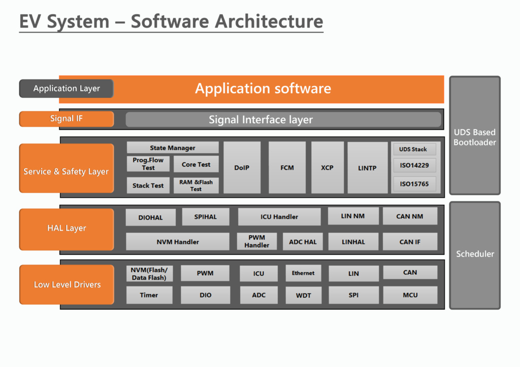
Interface Layer: The role of the IF layer is to act as an interface or a bridge between the application layer and the other layers of the motor controller platform. The Application Layer (not part of our platform) will host all the OEM-specific applications. .
Service, Safety and Utility Layers: These are the most important layers in terms of functionality. The coveted Field-Oriented Control algorithm is part of these layers, along with other safety, in-vehicle networking and vehicle diagnostics stacks.
Now let’s have a more detailed overview of the software architecture:
- FOC Algorithm: Field-Oriented Control is a vector control for electric motors. The torque produced using a scalar control method creates oscillations, thus impacting the efficiency adversely. FOC algorithm, with the help of mathematical calculations (facilitated by the microcontroller), can maximize the efficiency of the electric motors such as PMSM motor or a Brushless DC Motor.FOC does this by decoupling the torque and the electromagnetic flux generated by the motor. When this decoupling is achieved, the torque can be controlled independently without interfering with the electromagnetic flux.
Also, using FOC algorithm, PMSM and Brushless Motors can be operated smoothly over a wide range of speeds. Looking at it from an EV perspective, FOC is capable of driving an electric motor to generate quick acceleration and deceleration.
- UDS Stack (ISO 14229): UDS software is included for Off-board diagnostics. The diagnostics trouble codes when captured are stored in the EEPROM to be retrieved later in the garage.
Other modules like LINTP, XCP, FCM, Stack Test, CPU Load etc. are also included for safety, in-vehicle communication and fault handling.
Hardware Abstraction Layer: HAL comprises of the routines and functions that lets the upper layers interact with the ECU hardware. As seen in the diagram, CAN Network Management, CAN Interface, LIN Network Management, ADC etc. are some of the protocols for which HAL has been included.
The Hardware Abstraction Layer in this motor control system comes in handy when the algorithms need to be migrated to a different MCU family.
Low-Level Drivers: LLDs is the basic microcontroller peripheral. It has no idea about the nature of the value that it is receiving from the microcontroller. Its job is to pass on the value to the HAL where the value will be converted to a physical value.
For example, the LLD measures a current value which is 0-5 V. When this value is received by Hardware Abstraction Layer, it is converted to a physical value of 0-30 A. LLDs for PWM, ADC, LIN, CAN and MCU are included in the bottom-most layer of our EV motor control system.
The hardware platform that supports our FOC algorithm and other software stacks is also a very crucial part of the EV motor control unit. Let’s have a quick overview of the underlying hardware.
Hardware Architecture Powering Our EV Motor Control System ECU
Our EV Motor Control Unit has been designed on an Automotive-grade, Dual Core Microcontroller platform– 32 Bit TI Delfino.
The Control Board (Microcontroller) receives inputs from:
- Vehicle Sensors: Including the throttle sensors, brake sensors, Torque sensors over an Analog channel. Data received from these sensors are fed into the FOC algorithm for mathematical computation of PWM signal. This signal drives the electric motors.
- LIN, CAN and UART Transceivers: Messages from other ECUs are received through CAN, LIN or UART protocols. The respective transceivers act as an interface between the in-vehicle networking protocols and the physical medium (CAN BUS/LIN Bus/RS 232)
- OBDII CAN: OBDII protocol also communicates with the microcontroller board for emission related data.
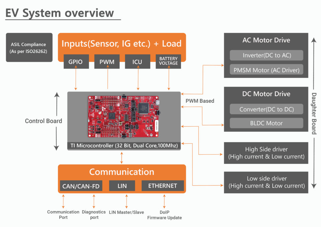
This EV System overview will give a better understanding.
Based on these inputs, the Field-Oriented Control algorithm directs the MCU to generate PWM signals. These signals are sent to the Daughter Board (Power Board).
Daughter Board, as explained earlier, is the power management system of our EV Motor Controller unit. Also called as the power board, it is responsible for generating the current supplied to the electric motors. As mentioned earlier, it consists of varying number of MOSFETS for this purpose.
The addition of the Daughter Board has made our motor controller platform a highly flexible and a universal solution for Electric Vehicle Applications. Whether you need to drive a smaller BLDC or PMSM motor or a bigger one, the MCU remains the same. All one needs to customize is the small daughter board
Customizations Required to Cater Different Use-Cases of EV Motor Control Unit
The customizations for different use-cases essentially boils down to
- the number of MOSFETS
- the power capacity of the MOSFETs. (that are integrated with the Daughter Board
Higher the power rating of the motor, larger the number and rating of the MOSFETs. For instance, our prototype motor control system designed for a 5 KW BLDC motor has 6 MOSFETs in parallel on each side of the board.
Now to drive a smaller EV, say an electric 2-Wheeler that requires a 1 Kw motor, the daughter board will require only 2 smaller MOSFETs. Other supporting hardware components will also be based on the electric motor’s power rating.
Final Remarks
As quite evident from its design, our EV motor control system ECU is designed to cater to the changing needs of the Electric Vehicle industry. The segregation of motor drive logic (FOC algorithm) and power management aids in faster turn-around time of EVs. For a Demo of our Motor Control system for Electric Vehicles, please contact us at sales[at]embitel[dot]com.
Connect With Us
+91 80 41694200
+49 (0)711-60 17 47-788 / 789
+49 (0)711-60 17 47-789
+1-248-385-2017
+49 170 1688028
Product Engineering
Head-up Display
Infotainment
J1939 Stack
OBD 2 Stack
Bootloader Software
ISOBUS Stack
Telematics Platform
ECU Development
AUTOSAR
HMI/UI Development
IoT
Embedded Software and Hardware
Digital Commerce
Ecommerce Consulting
Ecommerce Platform Design
Ecommerce Platform Development
Ecommerce SEO & Marketing
Ecommerce Managed Services
Ecommerce Hosting
Magento Ecommerce Development
Magento 2 Migration Service
Mobile App Development
Ecommerce Service Suite
Hybris Ecommerce Development


