


Tech behind Telematics Explained: How does a Vehicle Telematics Solution Work?
“Telematics is the Talk of the Town” – this won’t sound as an understatement to the enthusiasts of the Automotive Industry!
A lot has been written and spoken about how Vehicle Telematics features are shaping the future of fleet management, remote vehicle diagnostics, vehicle/asset tracking, Insurance Telematics, e-call/b-call and more
But we wanted to understand the tools and technologies that are necessary for design and development of a Vehicle Telematics solution.
And hence the idea of sharing this information with our Automotive Community was conceived.
How does a vehicle telematics solution work?
A Vehicle telematics solution consists of the following 3 fundamental building blocks:
- Telematics Control Unit
- The Telematics Cloud Server
- The Front End- Web app and Mobile App
The following block diagram features the basic building blocks of an automotive telematics system.
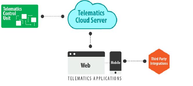
The Telematics Control Unit (TCU), which is the central hardware module of the telematics device, has communication interfaces with the in-vehicle network (CAN Bus) and the back-end cloud server( GPRS) .
TCU collects the crucial vehicle data such as diagnostics data, real time location, and speed of the vehicle (through different interfaces) and sends them to the cloud server over wireless network such as GPRS/cellular/LTE , in a specific packaged format.
This telematics data stored in the Cloud Telematics Server is accessed by the end-users through a web app or a mobile app.
Understanding the Telematics System architecture
Now, let us individually look at each of these components of telematics system and see how information flows between each of them.
- Telematics Control Unit(TCU ):
The Telematics Control Unit( TCU ) is the central component of a telematics system managing numerous functions such as:
- Collecting vehicle data via CAN-BUS port
- Managing information collected over various communication interfaces such as CAN, GPS, UART, GUI etc.
- Memory and battery management
- Managing two way communication with the Telematics Cloud Server
- Managing the communication with the user dashboard/HMI device
The telematics control unit (TCU) makes use of a set of hardware and software modules for efficient execution of these functions. Let us have a look at these hardware and software components in detail.
(Please refer to the following architecture diagram for a better understanding of the Telematics Control Unit.)
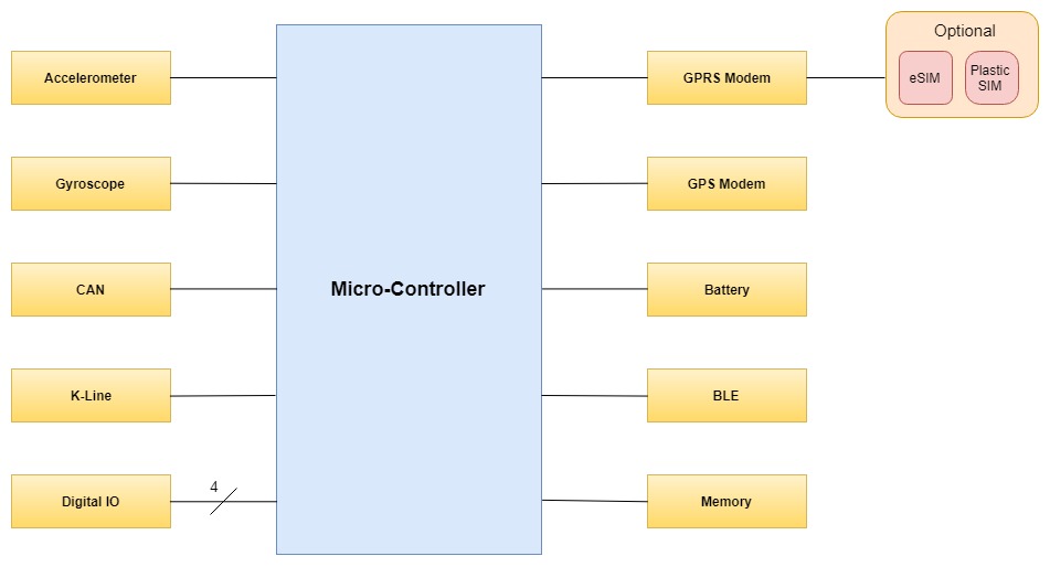
Image: Technology architecture of a Telematics Control unit The basic framework of a TCU hardware architecture comprises of :
- A Global Positioning System(GPS) module, for tracking the information associated with the latitude and longitude of the vehicle.
- A Central Processing Unit, with memory management and data processing capabilities. Commercially available telematics systems are based on microcontrollers, microprocessors or even Field Programming Gate Array (FPGA) for managing multiple processes occurring within the TCU.
Linux based processors have become popular for advanced display based telematics product development.
On the other hand, for basic telematics systems, Android based processors are popularly deployed.High performance processor from Telit Devices, Renesas Electronics, and ST Microelectronics are commonly used for developing efficient telematics system
- A CAN Bus module that manages all the communication with the vehicle ECUs. Many of the commercially available telematics devices also support OBD II, MOST, LIN interfaces.
The TCU communicates with the vehicle ECUs through CAN bus and fetches crucial information such as engine performance, vehicle speed, data from the Tire Pressure measuring Sensors, etc.
A telematics system may also use K/Line bus to alert the user about theft (by notifying the user if the vehicle is switched on by anyone), or to enable remote locking and unlocking of the vehicle.
- A Memory unit, which is necessary for storing information during an unreliable or no network conditions; or in some cases, to store vehicle data for future use.
This memory module is also useful for supporting advanced telematics functionalities like speech recognition.
Flash and Dynamic random-access memory are some of the commonly used memory types in a vehicle telematics system.
- Communication interfaces to support a wide range of communication including Wi-Fi, cellular, LTE etc.
- A GPRS module for data connectivity and in some cases voice based communication with remote devices. Often the GPRS module comes with a sim card, e-sim card or plastic sim cards, in addition to the GPRS modem to enable communication with remote devices over the cellular network.
- An in-built Battery module, with voltage rating of 3.2 to 3.4 volts, for integrated power management. The battery system is useful in a range of scenarios like :
- As a cost-effective backup source for Real-Time Clocks when the vehicle engine is off
- For Accessing telematics data ,for tracking and recovering stolen vehicle, when vehicle is switched off
- Bluetooth Module, to connect nearby devices with the telematics device, for interfacing with the end-user’s mobile phone for hands-free calls, text messages etc.
- Microphone with Audio interface to enable features such as hands-free calls, voice based commands. It also supports stereo based output to play media files from the vehicle audio system.
- A General Purpose Input/output interface (GPIO) system to connect lights, buttons. This includes both analog and digital I/O type interfaces.
- The HMI/user interface device to showcase crucial information such as navigation maps, vehicle speed , fuel usage etc. The user can use the HMI to access features such as hands-free calls on the move, view map, playing media files etc. The HMI is connected to the TCU through a GUI or HDMI port.
Overview of the Telematics Software Components
An automotive telematics system comes with the following set of software components:
- The Bootloader software stack for boot implementation
- Real Time Operating System (RTOS) and BSP modules
- Automotive Framework Classes that help the applications to access the primary telematics functionalities such as GPS data.
- Global Navigation Satellite Systems (GNSS) software for real-time vehicle tracking and identification of the geo location.
- Software for integration of data analytics to alert user about vehicle maintenance, fuel usage, vehicle usage patterns etc.
- Software for Multimedia device drivers.
- Device management software for Remote Over the air update of firmware ( FOTA) and software ( SOTA) images.
- Security Algorithms for ensuring multi-level security of the telematics code and application through device and user authentication, data encryption, Content Filtering etc.
- Cloud Telematics Server:
Now the information collected by the TCU is sent to the cloud based telematics server through a GPRS/cellular network over HTTPS . But before the transmission, the data packets are encapsulated into MQTT messages.
Once the data packets reach the cloud, data is extracted and stored into a database for further processing.
The Cloud based telematics server consists of a web server, an application server, and a database.To learn about the data flow within a cloud application, also read: How an IoT Cloud Application Works? A Deep Dive into the Software Architecture and Data Flow.
The web server and application server ensure a seamless exchange of data between the database and front-end application, often a web app or a mobile app.
- The Front End:
The data stored in the telematics server can be accessed by the end user using either via a desktop or mobile application. Based on the specific use case, the telematics data in the server can be fed into a third party software such as computerized mapping software, to apply further business logic on the available data.
Integration of Telematics with Web/Mobile Apps
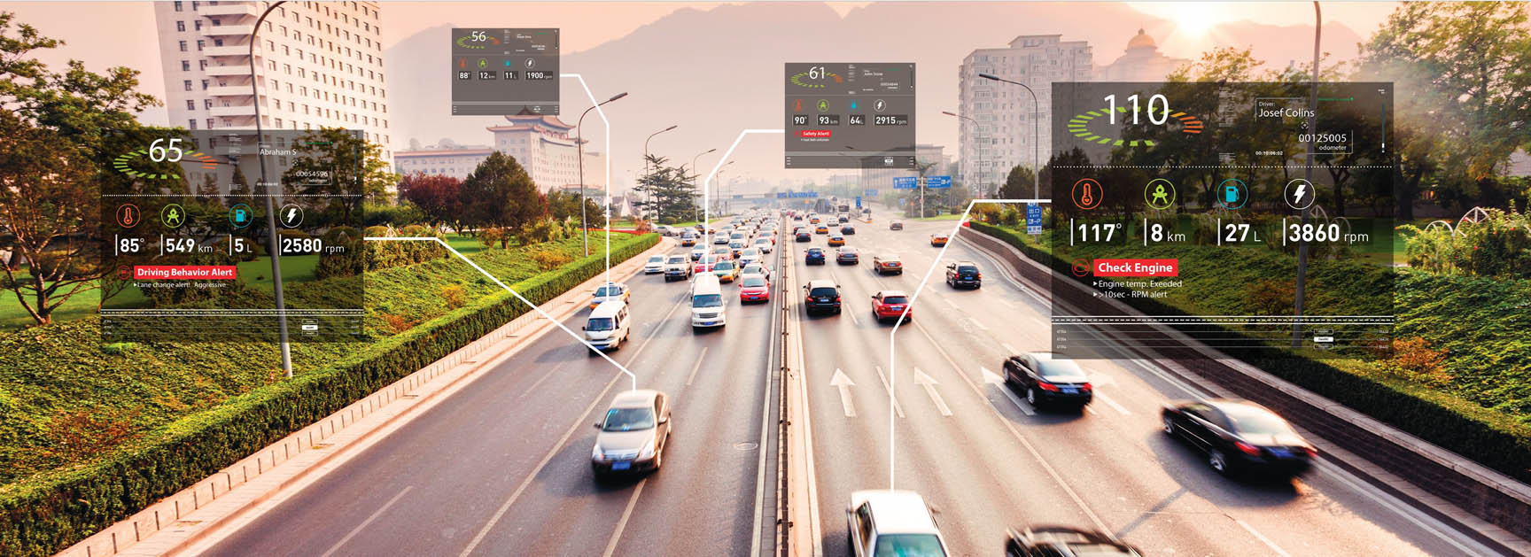
The telematics information when integrated with a smartphone or web app, offers numerous business opportunities for various automotive stake holders. We will have a brief look at a few such scenarios relevant in current times:
- The fleet management service providers use the telematics information for real-time time fleet tracking, remotely monitoring the driver, optimizing fuel usage, gain business intelligence based on analysis of vehicle data among others.
- Telematics has paved way for a new model of insurance – Usage Based Insurance whereby the automotive insurance companies use the telematics data to serve and charge the users based on vehicle usage pattern.
- Telematics allows daily commuters to : set a notification based maintenance schedule so that they are intimated when their vehicle needs a maintenance service, to track stolen vehicles ,use location based services like enhanced navigation, traffic related information- using a desktop or mobile app.
- The advent of telematics solutions has supported the growing popularity of ride sharing services for daily transits. Telematics technology enables both the ride-sharing companies and the passengers to keep a closer tab on the driver, manage payments based on the ride maps, monitor the vehicle movement through their smartphones – all in a seamless and secure manner.
Hope you liked this blog on automotive telematics technology. If you are interested to know more about the hardware and software features of a telematics system, please get in touch with our IoT consultants.
This entry was posted in Embedded Blog, Blog by Embitel. Bookmark the permalink
SUBSCRIBE
ASK OUR EXPERTS
POPULAR TAGS
RELATED SERVICES
Car HUD (Heads-up Display)
Go-to-market in 6 months with our automotive grade hardware and software design
Automotive Control Units
Electronic Control Units (ECU) development services for Body Control Modules (BCM), Powertrain, Chassis and Infotainment
AUTOSAR Software Services
AUTOSAR MCAL development, RTE and BSW integration, Application Layer development, Tools configuration and code generation
CUSTOMER SUCCESS STORIES

J1939 Stack for advanced EPS system
Find out how J1939 stack resolved on-chip memory issue for an Automotive Tier-I supplier

Software re-engineering | Telematics applications
Modular architecture re-design across fleet management product lines - GPS fleet security, vehicle and trailer tracking

IoT based Home Automation system
Design and development – Sensor Networks, Custom IoT gateway, Cloud and Mobile App


