


How Important is Dependent Failure Analysis in Achieving ‘Freedom from Interference’ as per ISO 26262?
An automotive system consists of multiple software components that interact with each other.
For instance, a light outage detection ECU communicates with UDS based diagnostics to report outage in LED light system. Any fault in the light out detection ECU might lead to incorrect diagnostic reporting.
In the context of ISO 26262 compliant automotive software development, the scenarios get more complicated and nuanced. The standard mandates that a lower ASIL component can access a function of a higher ASIL component only when there is no interference and dependence. In other words, a fault in a lower ASIL component must not affect the functioning of a higher ASIL component.
We can take an example of ADAS to understand the extent of this interference. An ASIL B communication module might feed some data to a cruise control module so that the module can take the right decisions in terms of braking and speed control. An instance where the communication module develops some glitch and is not able to feed the right data, can be catastrophic. So how do we avoid such situations? Do we assign higher ASIL to every vehicle component? That would escalate the cost by a significant amount, which is definitely not recommended.
This is where Dependent Failure Analysis (DFA) can prove to be very effective.
In the subsequent sections, we will try to co-relate dependent failure analysis and Freedom From Interference (FFI). We will examine what goes into dependent failure analysis and how it helps in achieving freedom from interference.
But first, let us understand the dependencies among the components and the types of faults to watch out for.
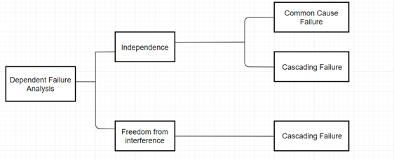
Understanding Independence, Interference and Freedom from Interference
We mentioned earlier that a fault occurring in one component might have a bearing on another component/s as well. Failure due to these faults are called dependent failures.
When we dig deeper into these failures, we are able to establish their cause and effects.
- When a failure is due to a single specific event or root cause that causes failure of multiple events, it is called common cause failure.
- Another kind of dependent failure is cascading failure. In this scenario, failure of one element leads to failure of another. It appears like a cascade of failures, hence the name.
Automotive Functional Safety consultants use the term independence only when the dependent failures (cascading and common cause failures) do not lead to any safety goal violation.
Independence can be ascertained by performing a dependent failure analysis (DFA), which we will discuss later in the blog.
Another term that we must understand before we explain dependent failure analysis is interference. We can understand interference as partially opposite of independence. It is the presence of cascading failure from a non-ASIL or a lower ASIL component to a higher ASIL component that leads to one or many safety goal violations.
Finally, freedom from interference implies absence of cascading failure between elements that leads to safety goal violation. Remember that it does not include common cause failure.
Dependent Failure Analysis, Freedom from Interference and Independence: How Are These Related?
Now that the terms related to dependent failures are clear, we can move to the analysis that help achieve freedom from interference and also independence (hope you are able to identify the difference between the two 😊).
Dependent Failure Analysis focused on finding the single causes/events that invalidates independence and freedom from interference. Every element that might cause such failures are taken into consideration while performing this analysis. Part 6, Part 7, and Part 9 of the ISO 26262 standard document serve as the reference for performing dependent failure analysis.
Some points to remember about dependent failure analysis:
- It validates Freedom from Interference between the elements by identifying the cascading failures
- It validates independence between the elements by identifying both cascading and common cause failures
- Dependent Failure Analysis helps in putting in place appropriate safety mechanisms to contain the faults within the element and prevent it from cascading
- Dependent Failure Analysis can be performed at system, software, and hardware level
- The analysis brings forth the points that are susceptible to failures
- It can be performed with both deductive and inductive approaches
What Goes into Dependent Failure Analysis? Stepwise Explainer
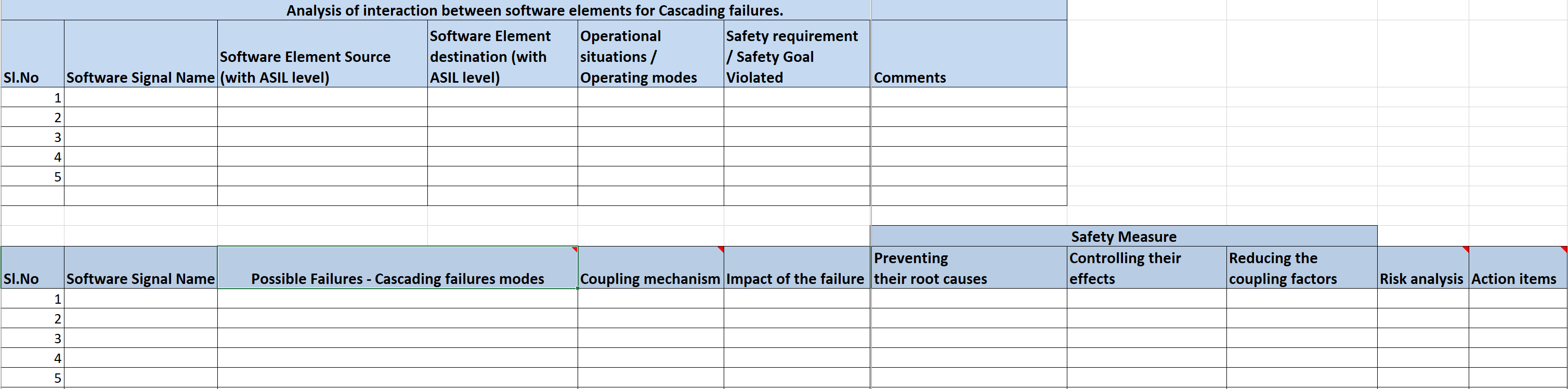
Identification of the cause of the failure for all safety-critical elements are recorded in a worksheet. ISO 26262 consultants use tools or regular excel sheets to create the template. Some of the tools that are widely used for dependent failure analysis are Vector PREE Vision, ANSYS medini analyze, ENCO SOX and LDRA tool.
Irrespective of whether you are using tools for analysis or an MS excel sheet, the worksheet has two tabs, one for Cascading Failures (CF) and one for Common Cause Failures (CCF).
Here’s how a typical dependent failure analysis worksheet looks like:
Let’s delve a bit deeper into both CCF and CF analysis.
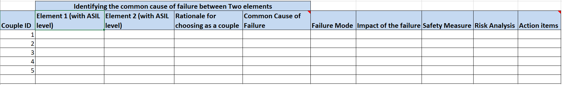
Common cause failure analysis begins with identifying the elements for which common cause of failure have to be identified. The reason for choosing a couple of these elements must be explained by the engineers. Typically, these activities are performed by automotive experts who are able to identify the elements based on the architecture and their extensive experience in automotive domain.
Some factors that influence the selection of the elements are:
- One software implementing different functions
- Partitioning of software
- Redundant elements
- Same external resource controlling two elements
Following are the aspects based on which the analysis is performed:
- Root Cause of the Failure: The root cause of failure is the common cause (single specific event) that affects both the elements chosen for analysis. For instance, signal processing fault might affect two elements of an LED ECU.
- Failure Mode: These are project-specific failure modes of the elements. Failure modes can be anything from loss of function to degraded functions and unintended activation or deactivation of the element’s function.
- Impact of the Failure: The impact of each failure is documented in this section. Impact at both local and system levels is analyzed. In the context of an LED control ECU, inconsistent switching on and off of an LED can mislead the operator or the driver.
- Safety Measure: The existing safety measures for handling such failures are described in this section. Details about prevention of the root cause and controlling their effects are also an integral part of the analysis and is mentioned here. For instance, if adherence to some automotive standards like CISPR, ISO 11452 etc. can prevent the cause, it must be included in this section.
- Risk Analysis: The risk analysis needs to be performed & documented. If the risk is found to be within the acceptable limits as per the project requirements, then no action is needed, i.e., the action item column in the template need not be filled. If the risk is found to be high & the project decides to change the design, then the action items shall be filled with the change request or the planned changes to mitigate\handle the risk.
- Action Item: The design changes resulting from the CCFA constitute the action items. These are changes that are required to be made to the design in order to keep the impact of the failure as localized as possible.
Cascading failure is analyzed between the source element (origin of fault) and destination element which is the final failure perceived by the vehicle driver. These elements are identified during the software architecture design activity. Analysis of data exchange between source and destination elements is performed in order to identify the signals transmitted by source element that caused the cascading failure.
The ASIL assigned to the source and destination element between which the data exchange took place is also analyzed. It is also extremely important to consider the operating modes and situations that are relevant to the cascading failures and hence, must be listed.
Apart from these factors, failure modes, their impact, and ways to control them are analyzed and documented. These analyses go a long way in achieving freedom from interference and identifying the design changes required to reduce the risk of dependencies.
Following possible failures must be looked out for during cascading failure analysis:
Timing and Execution: Timely execution of processes is paramount to automotive software. Failures such as blocking of execution, execution deadlocks, processes going to infinite loop, incorrect time allocation for execution and issues with synchronization among the elements are some of the failures related to time and execution that must be analyzed.
Memory Corruption: If an element is corrupting the memory of another element or accessing the memory that is allocated to a different element, it can lead to cascading failures. Such interactions must be identified and documented.
Information Exchange: The information exchange between the elements must be accurate and there must not be any loss, repetition, corruption, and delay in information exchange. Other factors such as incorrect addressing, information sequence also need to be analyzed.
Conclusion
ISO 26262 standard makes different analyses a very important part of safety lifecycle. Dependent failure analysis is one such analysis that helps achieve freedom from interference and independence. It demonstrates that requirements to reduce the dependencies between the elements have been met and are in sync with the technical safety requirements and functional safety requirements. At the end of the analysis, the engineers have clear insights on the common and cascading failures which help them reinforce the safety measures.
This entry was posted in Embedded Blog, Blog by Embitel. Bookmark the permalink
SUBSCRIBE
ASK OUR EXPERTS
POPULAR TAGS
RELATED SERVICES
Car HUD (Heads-up Display)
Go-to-market in 6 months with our automotive grade hardware and software design
Automotive Control Units
Electronic Control Units (ECU) development services for Body Control Modules (BCM), Powertrain, Chassis and Infotainment
AUTOSAR Software Services
AUTOSAR MCAL development, RTE and BSW integration, Application Layer development, Tools configuration and code generation
CUSTOMER SUCCESS STORIES

J1939 Stack for advanced EPS system
Find out how J1939 stack resolved on-chip memory issue for an Automotive Tier-I supplier

Software re-engineering | Telematics applications
Modular architecture re-design across fleet management product lines - GPS fleet security, vehicle and trailer tracking

IoT based Home Automation system
Design and development – Sensor Networks, Custom IoT gateway, Cloud and Mobile App


