


The Critical Role of Safety Mechanisms in ISO 26262 Compliance
The fusion of innovation and safety dictates the pace of progress in the automotive realm. While innovation is largely brought about by enhancing the electronic systems in a vehicle, safety concerns come as a by-product. And that’s where ISO 26262 standard comes into the picture- to ensure that functional safety is not left behind in the race to automation and connectivity.
As we delve into the world of modern vehicles, we encounter an array of sophisticated features, from autonomous driving capabilities to interconnected infotainment systems.
The importance of ISO 26262’s safety mechanisms becomes increasingly apparent in this context. They serve as the foundation upon which the future of automotive reliability and passenger safety is built.
For instance, in advanced driver-assistance systems (ADAS), safety mechanisms play a pivotal role in maintaining operational integrity, even in the face of component failures.
Consider a vehicle equipped with level 3 autonomy, where multiple sensors and cameras are employed to perceive the vehicle’s environment. This system integrates redundancy for critical sensors, ensuring that if one fails, another can take over seamlessly, allowing the vehicle to continue its journey safely.
Furthermore, sophisticated watchdog timers, another set of safety mechanism, monitor the system’s performance, ready to initiate a safe mode if anomalies are detected.
How do ISO 26262 Experts Derive Safety Mechanism?
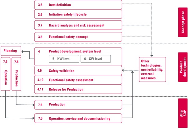
The derivation of safety mechanisms is intrinsically linked to the ISO 26262 safety lifecycle. It outlines a comprehensive approach to managing functional safety throughout the development of automotive systems.
This lifecycle is segmented into phases that span from the conceptual inception of a product through to its decommissioning, ensuring that safety considerations are integrated at every stage.
Within this framework, safety mechanisms are most prominently conceptualized, designed, and verified during specific phases of the lifecycle.
Here’s how they relate:
- Concept Phase (Part 3 of ISO 26262): The journey begins with the Concept Phase, where the initial Hazard Analysis and Risk Assessment (HARA) is conducted. This phase sets the foundation for safety by identifying potential hazards and defining the safety goals, laying the groundwork for the subsequent derivation of safety mechanisms to mitigate these risks.
- Product Development: System Level (Part 4 of ISO 26262): Moving into Product Development at the System Level, the functional safety requirements are specified based on the safety goals identified earlier. It is in this phase that the Functional Safety Concept is developed, detailing how each safety goal will be achieved through specific safety mechanisms.
This marks the phase where safety mechanisms are directly derived and elaborated upon. A critical bridge between abstract safety goals and their practical implementation is thus formed.
- Product Development: Hardware and Software Level (Parts 5 & 6 of ISO 26262): As the lifecycle progresses to the Product Development at the Hardware Level and Software Level, the technical safety requirements become the focus.
Here, the safety mechanisms identified in the system level are further refined and integrated into the hardware and software design. This includes the development of redundant architectures, error detection and correction protocols, and other mechanisms tailored to mitigate identified risks.
What are the Typical Safety Mechanisms Deployed in ISO 26262 Compliant Automotive Solutions?
Challenges faced in ensuring functional safety for automotive solutions are unique for each project. Safety mechanisms vary accordingly. Operating conditions, ASIL rating etc. dictate the kind of safety mechanism needed to be deployed. Another important factor about implementing safety mechanisms is the level at which they must be deployed. Let’s understand this aspect in more detail:
Hardware Safety Mechanisms
- Redundancy: This involves duplicating critical components or systems so that if one fails, the other can take over. Redundancy is vital for functions like braking and steering, where failure could lead to catastrophic outcomes. For instance, modern vehicles might have multiple brake circuits, ensuring that if one circuit fails, the vehicle can still be brought to a stop safely.
- Watchdog Timers: These are used to monitor the system’s operation and ensure that it is functioning within expected parameters. If a software or hardware component becomes unresponsive, the watchdog timer can reset the system or put it into a safe state. This mechanism is crucial for preventing system lock-ups that could lead to loss of control.
- Error Detection and Correction (EDAC) Codes: EDAC codes, such as Parity Bits and Error Correction Codes (ECC), are used in memory and communication systems to detect and correct errors automatically. They help maintain data integrity, ensuring that even if data gets corrupted during transmission or storage, the system can identify and rectify the errors, preventing malfunction or data loss.
- Safe Shutdown Circuits: These circuits ensure that, in the event of a failure, the system can be safely powered down without causing additional hazards. For example, if a fault is detected that could lead to overheating or fire, safe shutdown circuits can disconnect power sources, preventing further damage.
Software Safety Mechanisms
- Error Handling and Recovery: Software is designed to detect errors and either correct them or enter a safe state. This could include mechanisms for retrying operations, using backup data, or switching to a reduced functionality mode that maintains critical operations while minimizing risk.
- Safe State Management: In the event of a detected fault, systems need to transition to a “safe state” where no harm can occur. This might mean disabling certain functions, engaging emergency brakes, or moving to a minimal operational mode until the issue can be addressed.
- Redundancy and Diversity: Similar to hardware, software redundancy involves having multiple software components that can perform the same function, so if one fails, another can take over. Diversity means having these redundant components developed using different methods or algorithms to reduce the risk of a common cause failure affecting all components simultaneously.
- Safety Interlocks: These are checks or conditions that must be met before certain operations can proceed. For example, a vehicle might prevent the engagement of the autonomous driving mode unless all required sensors are operational, or it might not start if the driver’s seatbelt is not fastened.
- Runtime Monitoring: Software routines continuously monitor the operation of both hardware and software components during runtime. This can include checking for out-of-range values, unexpected states, or the integrity of communication between components, triggering corrective actions if necessary.
Integrating Robust Safety Mechanisms in ISO 26262 Compliant Motor Control Development
To get a better understanding of how safety mechanisms work to mitigate functional safety hazards, let’s consider an example of motor control solutions. The application of motor controller in the vehicle decides its safety criticality. The more advanced use-cases include electronic steering control, ABS, etc, and they are mostly assigned ASIL D, the most stringent ASIL rating.
The adaptation of safety mechanisms into the development process of motor control solutions can be understood through a structured framework, encompassing system design, hardware considerations, and software strategies.
Safety Mechanisms for Motor Controller at System Design Level
- Embracing Redundancy: A motor control unit that controls a vehicle function such as electronic power steering cannot afford to lose its function. Implementing redundancy within a motor control system means designing the system with backup pathways that can seamlessly take over in the event of a failure, ensuring that there is no loss of functionality.
Imagine a vehicle equipped with an electric power steering system, which is crucial for the driver’s ability to control the vehicle. For redundancy, the system could be designed with two motor control units (MCUs) operating in parallel.
Each MCU independently receives input from the vehicle’s steering sensor but only one MCU actively controls the steering motor under normal conditions. If the primary MCU fails, the secondary MCU immediately takes over, ensuring that the steering function remains unaffected.
- Implement Watchdog Timers: The motor control ECU must be incorporated with watchdog timers. These timers can reset the motor control system or trigger a safe mode operation if the system becomes unresponsive. Such an arrangement ensures that “software freezes” do not lead to hazardous situations.
Let’s continue with the earlier example of an electronic steering control. Under normal operation, the system’s software resets the watchdog timer at regular intervals, well within the timer’s countdown.
However, if there’s a software issue that causes the control loop to freeze or run too long, the watchdog timer would reach zero. Recognizing this ‘failure to reset’ as a sign of system unresponsiveness, the watchdog timer then triggers a predefined response.
It could instruct the system to enter a safe mode, where the steering assistance is reduced or turned off in a controlled manner, alerting the driver through dashboard indicators that manual steering is required.
- Design for Overcurrent and Overvoltage Protection: Should the motor control system experience an overcurrent condition due to a short circuit, an overcurrent protection circuit would cut off power to the motor to prevent damage.
Similarly, overvoltage protection safeguards the system against voltage spikes that could harm electronic components.
- Secure Data Communications: To ensure secure firmware updates to the motor control system, encrypted communication channels are used. This prevents unauthorized modifications, ensuring that only verified and secure firmware versions are installed.
Safety Mechanisms for Motor Controller at Hardware Level
Safety mechanisms at hardware level have special importance in ISO 26262 compliance. Hardware serves as the foundational layer of defense against risks and associated hazards.
Unlike software, which can be updated or patched relatively easily, hardware forms the immutable backbone of system architecture, making its initial design and integration of safety mechanisms vital for long-term performance and safety.
Here’s a few hardware level safety mechanisms with respect to motor control system:
- The integration of Built-in Self-Test (BIST) features within the hardware layer underscores a proactive approach to safety. This enables regular diagnostic checks that support early fault detection and system reliability.
- Error Correction Codes (ECC) emerge as heroes in maintaining data integrity, adept at identifying and correcting errors. Such errors, if go undetected, could mar memory and data transmission.
- The role of Safe Shutdown Circuits is of utmost importance as they ensure that even in the face of unexpected power losses or faults, the system can power down safely. Such safety mechanism helps in avoiding data corruption and hardware damage.
- Isolation barriers serve as crucial fortifications, segregating parts of the system to prevent the spread of electrical faults, thereby minimizing the risk of cascading failures.
- Monitoring of temperature and voltage plays a pivotal role in preempting potential hazards, enabling timely interventions that prevent overheating, voltage spikes, or thermal runaways.
- The design for Electromagnetic Compatibility (EMC) signifies a commitment to minimizing electromagnetic interference. This ensures the motor control unit’s safe operation amidst electromagnetic interference of all sorts.
| Function | Potential Failure Modes | Corresponding Technical Safety Mechanism |
| Speed Control | Over-speed, Under-speed | – PID (Proportional-Integral-Derivative) control adjustments based on real-time speed feedback. Dynamic braking integration for immediate deceleration |
| Torque Control | Excessive torque, Insufficient torque | – Real-time torque feedback loop with torque estimation algorithms. Adaptive torque limiting based on operational conditions |
| Position Control | Incorrect positioning, Oscillation | – High-resolution encoder feedback for precise position control. Advanced filtering and PID tuning to dampen oscillatory responses |
| Temperature Monitoring | Overheating, Thermal runaway | – Direct temperature sensing with thermistors integrated into control algorithms for dynamic thermal management. Activation of external cooling systems based on thresholds |
| Current Monitoring | Overcurrent, Short circuit | – Fast-acting current sensing circuits with digital signal processing for immediate response to overcurrent conditions. Programmable current limits with automatic shutdown |
| Voltage Regulation | Overvoltage, Undervoltage | – Precision voltage monitoring with ADC (Analog-to-Digital Converter) feedback. Software-controlled power converters for real-time voltage adjustment |
| Communication | Data corruption, Loss of communication | – CRC (Cyclic Redundancy Check) for data integrity verification. Timeouts and automatic retransmission of corrupted or lost packets |
| Emergency Stop | Inability to stop in an emergency | – Multi-channel input monitoring for redundancy in emergency stop signals. Immediate execution of predefined safe stop sequences |
| Power Supply Management | Power failure, Unstable power supply | – UPS (Uninterruptible Power Supply) integration for critical components. Voltage sag detection with seamless switch-over to backup power |
| Cybersecurity | Unauthorized access, Tampering | – Mutual authentication protocols and secure boot mechanisms. Real-time monitoring and anomaly detection to identify and mitigate cybersecurity threats |
| Packetization | Packet loss, Packet corruption | – Data fragmentation and reassembly algorithms to ensure complete data transmission. Use of sequence numbers and time-stamping to detect and correct out-of-order or lost packets |
| Clocking | Clock drift, Clock failure | – Synchronization protocols like PTP (Precision Time Protocol) for clock alignment. Independent watchdog timers to detect and correct clock discrepancies |
| System Reset | Incomplete reset, Failure to reset | – Supervisory microcontroller for monitoring and managing the reset process Implementation of hardware-based and software-enforced reset sequences |
Safety Mechanism for Motor Controller at Software Level
Modern motor control systems have complex algorithms controlling their speed and torque based on the use-case.
These software algorithms enable continuous monitoring of motor operation parameters, such as speed, torque, and temperature.
By analyzing this data in real-time, the software can detect anomalies that may indicate potential safety issues, like overheating or unexpected operational behavior. Upon detection, the system can automatically adjust operational parameters or shut down the motor to prevent damage or accidents.
Let’s look at some of the safety mechanism integrated at software level:
- Error Detection and Handling: The strategies that identify and correct data discrepancies come under this category of safety mechanism. They ensure smooth system operation even when faced with unexpected anomalies.
The motor control software uses cyclic redundancy checks (CRC) for detecting errors in data received from sensors. If an error is detected, the system can request the data again or use a default value to maintain operation while marking the sensor data as unreliable.
- Safe State Transition Management: These are the mechanisms that manage transitions between operational states in a controlled manner, maintaining safety throughout the system’s operation.
Software controls the motor’s state transitions, such as from acceleration to deceleration, ensuring that these changes occur smoothly and predictably to avoid creating unsafe conditions.
- Software Redundancy and Diversity: These safety mechanisms include approaches that introduce fault tolerance through parallel modules or diverse software strategies. Such mechanisms aid in mitigating common cause failures and enhancing system robustness.
For example, two separate software algorithms calculate the required motor torque. If the results differ beyond a predefined threshold, the system flags a potential error and can revert to a conservative operation mode or alert the driver.
- Safety Interlocks and Checks: These gatekeepers ensure all operations adhere to safety parameters, preventing unsafe conditions. This is achieved by verifying the integrity of inputs and monitoring system variables.
In the context of a motor controller, before enabling high-speed operation, the motor control system verifies that all safety conditions, such as proper engagement of the vehicle’s transmission and the absence of fault codes, are met.
- Fault Tolerance and Error Recovery: If a non-critical software module fails, the motor control system can bypass the module, allowing continued operation in a degraded mode until the issue can be addressed.
Conclusion
Looking forward, as automotive technologies continue to evolve, the role of safety mechanisms will only become more critical. Their ongoing development and refinement will be key to addressing the new challenges these technologies present.
Ensuring safety is paramount in automotive innovation. In this evolving landscape, following ISO 26262 guidelines with robust safety mechanisms is more than a regulatory must—it’s a fundamental aspect of automotive progress, showing the industry’s solid commitment to safety.
This entry was posted in Embedded Blog, Blog by Embitel. Bookmark the permalink
SUBSCRIBE
ASK OUR EXPERTS
POPULAR TAGS
RELATED SERVICES
Car HUD (Heads-up Display)
Go-to-market in 6 months with our automotive grade hardware and software design
Automotive Control Units
Electronic Control Units (ECU) development services for Body Control Modules (BCM), Powertrain, Chassis and Infotainment
AUTOSAR Software Services
AUTOSAR MCAL development, RTE and BSW integration, Application Layer development, Tools configuration and code generation
CUSTOMER SUCCESS STORIES

J1939 Stack for advanced EPS system
Find out how J1939 stack resolved on-chip memory issue for an Automotive Tier-I supplier

Software re-engineering | Telematics applications
Modular architecture re-design across fleet management product lines - GPS fleet security, vehicle and trailer tracking

IoT based Home Automation system
Design and development – Sensor Networks, Custom IoT gateway, Cloud and Mobile App


