×

Happy to Help!

This website doesn't store cookies. Enjoy the experience, without worrying about your data!

Great, thanks!

Monthly Archives: May 2019

  • 0

Have You Met Android Treble: An Introduction and Analysis of its Benefits for the Automotive Industry

Category : Embedded Blog

With no intentions of starting a ‘War of Words’ between the fans of the two most popular Operating Systems, we have one simple question for our  community of Software Developers.

[Hint – think software and answer this!]

What’s that one big difference you find, while using an iOS based device vs Android  device?

Did someone say OS Updates?

While iOS users can conveniently update their OS (mainly because of the OEM support), Android users have been struggling with OS updates since eternity.

And a major chunk of the problem is attributed to the fact that OEMs cannot update Android OS, without first updating the hardware platform/components. So for an Android device to run the latest version, the hardware needs to be separately and necessarily upgraded.

The problem translates into an even bigger one when we analyse it in the context of Automotive Sector.

Upgrading hardware frequently isn’t a feasible option for the automotive industry. And since end users cannot update their version of Android beyond what their hardware allows, at one point, they’re forced to use an outdated software.

But things are about to change, thanks to Android Treble!

Why Android Treble?

If we look at the sheer numbers, a quick Google search for “Android distribution dashboard” points out that more than 98% of Android devices are running outdated software. And this also includes the devices/products from the automotive sector (like Infotainment Systems and other multimedia applications).

Fortunately, Google has decided to bridge the age-old gap of devices with outdated OS and the ones with latest versions with the launch of the  Project Treble.

Finally, OEMs’, Suppliers or End-Users will be able to update their devices with the latest Android version without having to upgrade their hardware.

Through this post, let’s try to find out all that we can about Android Treble.

What is Google’s Project Treble?

As already pointed out, OEMs cannot update hardware as easily and frequently as software updates roll out.

Reasons –

  1. Replacing the hardware is very costly
  2. a lot of time and effort is required to re-design the interfaces between the existing hardware and the new OS versions.

Before Android 8.x, the OS framework and hardware-level framework were parts of the same code.

Project Treble

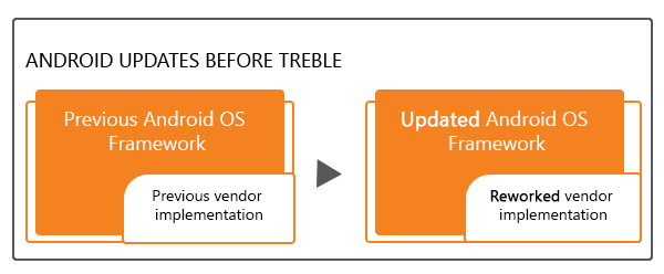
Android update process before the launch of Project Treble ; Image Source: android.com

So, whenever a new OS update was made available, to bring it into effect, the hardware-level framework also had to be updated necessarily.

But with the launch of Android 8.x, Google separated the two implementations, making it possible for Android OS to be updated without having to touch the hardware framework.

Andriod Treble

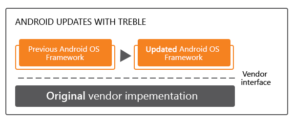
Android update process After the launch of Project Treble; Image Source: android.com

For a better understanding, consider this scenario. Your vehicle’s Android Infotainment System is tightly coupled with its hardware platform.

Let’s say it’s running on Android 7.x or an earlier version of Android (which would have been the latest OS version, when you purchased the vehicle/product). Now if an update needs to be pushed, low-level hardware drivers were also required to be updated along with the Android code. That in itself would be a mammoth task.

Now since the chip maker owns the code for these low-level hardware drivers, the Android update will have to wait until the chip maker updates its low-level code to make it compatible with the new Android OS.

With the release of Android 8.x and Project Treble, in particular, the hardware platform & associated device drivers have been abstracted and de-coupled from the OS code.

Therefore, the high-level software and OS can be freely updated to the latest version without having to wait for the chip maker to update its code. Thus theoretically, the entire update process is on the road to becoming much faster.

If you’ve grasped that, let us also give you a sneak-peek into the role of HIDL – an acronym for HAL Interface Definition Language.

The Role of HIDL in Android Treble

Before we dive into the nitty-gritties of HIDL, let us try to understand what an HAL is?  HAL, an acronym for Hardware Abstraction Layer forms an important software component of any Android Device.

Android’s software code communicates with the device’s underlying hardware through a hardware abstraction layer or HAL, and there are several HALs at work within an Android device.

At any point, there is an HAL for each hardware component (camera, microphone, etc.). So if any third-party app wants to communicate with a component of your device, for example, an image-editing app wanting to communicate with the camera, the camera specific HAL provides the driver-level communication channel for it to work.

Android System Architecture

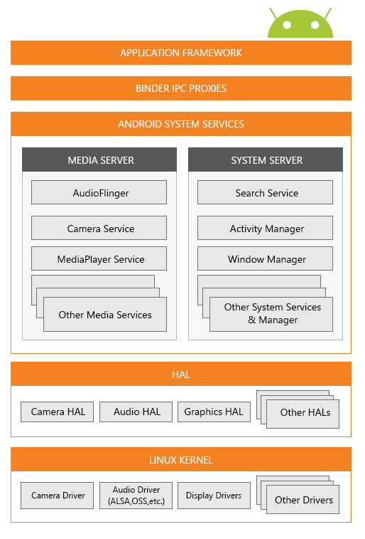
Android system architecture ; Image Source: android.com

Now, naturally, with the release of a new Android update for versions 7.x and earlier, all HALs would need to be rebuilt as part of the hardware update, before the OS update would be applied. And that would further complicate the whole story and increase the waiting time.

Thankfully, Android 8.x is set to re-architect Android OS framework. This change is the introduction of a new abstraction layer called the HIDL (HAL Interface Definition Language).

HIDL is a layer on top of the multiple HALs, and acts as a common interface between application layer and device components.

Now, to update the Android OS, only an update of the HIDL would be needed to make things work instead of having to rebuild all the HALs. Simple and efficient!

How Will B2B Businesses Benefit from Android Project Treble?

With the launch of Android Treble, the Android OS will become more secure and standardized, since there will be no need of re-designing the hardware layers to implement an update. IT support costs will drop since no hardware update will be needed The Requirements will become simpler, leading to faster and wider Android adoption since the update-challenge will be eradicated, thus, benefitting the B2B enterprises.

Significance for the Automotive Industry

Probably, Automotive would be one of the industries to gain a  significantly positive impact  from the implementation of Android Project Treble.

This initiative by Google will make it possible for enterprises to roll-out OS updates for Infotainment Systems without having to consider the hardware limitations.

Not only will it make the whole update process faster, but it will also increase the consumer base by a large margin, since people will always have access to latest features and security mechanisms irrespective of the underlying hardware platform.

Rounding it up

As a solution to overcome the OS update hurdles, Project Treble has all the necessary traits of a game-changer.

But implementing this solution as part of your Product Development Strategy would require extensive skills and in-depth understanding of the architecture of the Android OS (software layers as well as hardware intricacies).

For automotive OEMs, Suppliers and product companies, investing in the development of HIDL would be a wise decision in the long run.

There are two possible approaches to success – Either the skills to develop HIDL should be nurtured in-house or opportunities for a value-add partnership with a Product Engineering Services company, with necessary hardware & software skills, should be explored.

What is your take on Google’s Project Treble, does this sound like a value-add for your product development strategy? Let’s discuss – sales@embitel.com


  • 0

“Build or Buy the SCADA Solution?”: A Million Dollar Question Asked by every Enterprise before kick-staring their IoT Journey!

Category : Embedded Blog

The IoT powered SCADA solution, if leveraged to its full potential, has the capability to enhance the overall efficiency of your assembly line operations.

Reduced operational costs, enhanced flexibility, and higher asset availability, automated and intelligent maintenance workflows – these are some of the driving forces behind the growing popularity of the IoT Powered SCADA Systems.

In a nutshell, modern day SCADA has turned monitoring, controlling, interacting with industrial assets –into a seamless process that can be managed from anywhere, and anytime!

Curious to know how? Learn in detail about this in our tech blog: https://www.embitel.com/blog/embedded-blog/what-is-scada-system-and-software-solution

The Big Dilemma!

It can be said that the investment in SCADA solution acts as the stepping stone for enterprises aiming at leveraging the benefits of Industry 4.0.

But there is a tricky part here!

Enterprises who plan to invest in SCADA solution, as part of their Industry 4.0 initiatives face a critical dilemma: “Should we invest in an off-the-shelf or develop a custom version of SCADA solution?”

But how do you decide a SCADA solution investment strategy that:

  • Fits your budget and business requirements
  • Helps you achieve your industrial automation goals
  • Is easy to maintain and operate
  • Supports Future Scalability

Here is a video blog to help you resolve this dilemma

Why Watch this Video:

The video introduces you to an evaluation framework to wisely choose  between the two SCADA investment approaches.

The evaluation framework has two main components, the understanding and analysis of which is critical to decide between ‘off the shelf’ and ‘custom developed” SCADA solution.

The two components of the framework are the following:

  1. Business parameters:
    • Degree of Freedom
    • Total Cost of Ownership
    • After-Market Support
    • Time-To-Market
  2. Technical parameters, including:
    • Custom View of Enterprise Data
    • Workflow Automation
    • Interoperability & Scalability
    • Custom Designed HMI

Hope you will find this video blog helpful.

If you wish to receive notifications about our latest blogs, Please click on the subscribe button below.

Also, feel free to share the blogs using your social media handles by clicking on the icons given below!


  • 0

Brushless DC Motor vs PMSM: Find Out How These Motors and Their Motor Control Solutions Work

Category : Embedded Blog

Motors and Motor Controller Solutions have served Automotive Industry since time immemorial!

And the ongoing innovations in Motors and the Motor Control Systems have ensured that motors are becoming integral part of diverse set of Automotive Applications.

With efficiency as the motive, Motors and Motor Control Solutions are living up to the expectations of the Automotive Industry (including the Electric Vehicle space)

Interestingly, there are two specific types of Motors that have stood the test of time and have evolved tremendously.

They are popularly known as:

  • BLDC Motors – Brushless DC Motors
  • PMSM Motors – Permanent Magnet Synchronous Motors.

While BLDC Motors have replaced the Brushed DC Motors, PMSM Motors have come across as a better alternative to AC Induction motor.

Both these Motors find application in some of the most innovative automotive applications. For instance, PMSM is now the de-facto Motor deployed in the Drivetrain of Electric Vehicles.

Likewise, applications like Electric Power Steering and HVAC systems function at their best when a BLDC Motor drives them. However, these Motors can be sometimes deployed interchangeably, depending on certain specific use-cases.oHoweverHoHH

Before we delve deeper into the applications, let’s have a little understanding of How PMSM and BLDC Motors work?

In the course, we will also try to discuss about the inherent differences between these two motors.

How PMSM and Brushless Motors work?

  1. Brushless DC Motors

    A Brushless DC motor is an upgraded version of a brushed DC Motor. The absence of brushes gives BLDC motors the ability to rotate at high-speed and increased efficiency.

    Highlights of a BLDC Motors:

    • It has two major parts- a rotor and stator.
    • Rotor is the part that moves and has Permanent Magnets as Rotor Magnets.
    • Stator is the Stationary component and is made up of Coil Windings.
    • Electric Current through the Stator Windings generates a magnetic field which rotates the Permanent Magnet of Rotor.
    • By varying the Current flowing through the stator, the speed of the Motor can be varied.
    • In most Automotive Applications, the Motor Speed is controlled electronically, using a Brushless DC Motor Controller.

    *For in-depth details regarding the Motor Control Systems, please refer to our blog.

    Advantages of BLDC Motors:

    • Ability to work at higher speed and produce constant torque
    • Durability
    • Efficiency of almost 85-90%
    • Ability to respond to the control mechanisms at high speeds
    • No sparks and less noise, as the brushes are absent
    • Ease of Motor Control (using BLDC motor controller solutions)
    • Ability to self-start
    • Gets cooled by conduction and requires no additional cooling mechanism
  2. Permanent Magnet Synchronous Motor (PMSM)

    Moving on to the Permanent Magnet Synchronous Motor, it can be seen as an AC counterpart of the Brushless DC motor.

    PMSM also comprises of a Permanent Magnet as a Rotor and a Stator with a Coil wound over it. The working of PMSM Motor is also quite similar to the BLDC motor.


    PMSM Motor

    However, the change lies in the wave form of the Back EMF which is sinusoidal in nature. This is so because the coils are wound on the Stator in a Sinusoidal manner.

    It also implies that PMSM requires Alternating Current (Sinusoidal in nature) to achieve the best performance. This type of drive current also reduces the noise produced by the motor. We will discuss the concept of Back EMF in our upcoming blog on Field Oriented Control (FOC).

    The diagram will bring more clarity.

    Diagram:

    Advantages of PMSM Motors:

    • Higher efficiency than Brushless DC Motors
    • No torque ripple when motor is commutated
    • Higher torque and better performance
    • More reliable and less noisy, than other asynchronous motors
    • High performance in both high and low speed of operation
    • Low rotor inertia makes it easy to control
    • Efficient dissipation of heat
    • Reduced size of the motor

BLDC v/s PMSM Motors: Understanding the Motor Control mechanism

There is no major difference in motor control systems of BLDC and PMSM Motors; except the nature of the Drive Current and the detection of the Rotor Position.

While we have discussed the drive-current required for both the motors, let’s now talk about the importance of rotor position detection.

The right time to switching on the Motor Phase Current (motor commutation) is important in order to assess the correct amount of energy. In sensor-based motors, the HALL effect sensors do this job.

In a BLDC motor, the rotor position is usually detected by a set of 3 HALL effect sensors. The commutation is achieved through a six-step process. This results in small breaks in commutation which in turn causes torque ripples (periodic increase/decrease in torque output of the motor) at the end of every step.

A PMSM motor in contrast, requires only one HALL effect sensor as the commutation is continuous. Hence, the rotor position is monitored at every instance and is measured by the sensor and passed on to the PMSM Motor Controller Solution.

One of the advantages of PMSM motor is the absence of Torque ripple, which makes these motors more efficient than BLDC.

What are the Applications of BLDC and PMSM Motors in Automotive Industry?

Both BLDC and PMSM motors are widely used in the automotive industry, as both these Motors cater to the different kinds of use-cases (sometimes interchangeable.)

Brushless DC motors are durable, fairly efficient and low-cost. They can operate on high-speed and can be controlled electronically. All these attributes make these motors ideal for automotive components that are in operation, continuously.

PMSM motors on the other hand has every attribute of BLDC motor with added advantage of lesser noise and higher efficiency.

Let’s see some common applications of these motors, starting with Brushless DC Motors:

  • Electronic Power Steering Systems: The ability to work on high speed and inherent durability, make BLDC motors the preferred choice for Electronic Power Steering (EPS) Applications.

    A sensor-based BLDC motor can detect the position of the rotor and apply optimum torque to drive the steering wheel.

  • HVAC (Heating, Ventilation, and Air Conditioning) System: HVAC solutions are becoming smarter due to introduction of automation in the modern-day vehicles.

    This automation is brought about by the electronically driven motors, especially the Brushless DC Motors. These motors are controlled by Pulse Width Modulation (PWM) which makes it reliable, efficient and environment friendly.

  • Hybrid Electric Vehicle drivetrain: A large number of hybrid vehicles are integrated with Brushless DC Motor Controllers to drive the Drivetrain.

    There are several reasons for the same. Most important reason is the peak point efficiency and simple method of rotor cooling.

BLDC motors also aid in regenerative braking which is about charging the battery at every instance of braking. The Permanent magnets and the external torque work together as a generator to pulse-charge the battery.

Applications of PMSM Motors in Automobiles

  • Servo Mechanism in Automobiles: Servo mechanisms is a set of motors and motor controllers that produce motion at a higher energy level than the input applied. PMSM motors are the first choice of Motors to support such mechanism.

    This is because PMSM Motors are highly efficient, produce less noise and are resistant to wear and tear. One example is the servo brake that amplifies the force used by the driver on the brake pedals. Another example is the Servo Steering which is one step ahead of the regular power steering. This also makes use of a PMSM motor.

  • Electric Vehicle Drivetrain: Baring a few Electric Vehicles which use BLDC motors, most OEMs are deploying AC motors to power the EV drivetrain.

    And PMSM is the preferred choice. Reasons being high power density and the availability of efficient PMSM motor control solutions.

Towards the Future

New features are being introduced in the vehicles at an unprecedented rate. And motors, especially smart motor systems are at the core of such innovations.

Applications like ADAS are also driven by several small electronically driven motors.

And more importantly, as the world moves faster towards electric vehicles, the motors and motor control systems are destined to evolve at a much higher speed.

Because, that is only how the electric vehicles are going to get wider acceptance among the people who are so used to drive IC engine vehicles.


  • 0

[Video]What is A SCADA System? Find Your Answers in the ‘S’, ‘C’, and ‘A’ of a SCADA Solution

Category : Embedded Blog

SCADA a.k.a. Supervisory Control and Data Acquisition, is not a new kid on the block!

In fact, SCADA as an automation solution to Supervise/Monitor and Control the Industrial Assets, dates back to the 60s . From manufacturing sector to Food processing, Oil Refineries & more; a SCADA solution has found applications in various industries.

But with the introduction of Internet of Things (IoT), the business enterprises now seek a Smarter, Modular, Secure and Scalable version of SCADA.

IoT enabled SCADA system for Industrial Automation Applications

Modern day IoT based SCADA solution is emerging as a core component of Industrial Automation Solutions

IoT powered SCADA offers a seamless and efficient solution by supporting the following features:

  • remote monitoring of assembly line operations,
  • real-time reporting of equipment failures and other critical issues
  • In depth analysis of real-time industrial data

But how does SCADA perform these Supervisory and Control functions? Watch this video to find out:

What can you expect from this video? This video gives an overview about SCADA system by answering the some frequently asked questions such as:

  • What are the fundamental building blocks of an IoT based SCADA system?
  • How does SCADA help in Data Acquisition?
  • How does a SCADA enable automation of Supervisory Control?
  • What is the Technology Framework , that powers a SCADA Solution?

  • 0

Firmware Development for an NFC Based Driver Identification System

Category : IoT casestudies

About the Customer:

Headquartered in Europe, our Customer is a leading provider of Fleet Management System.

Business Challenge:

For businesses that own/manage Fleets of Commercial Trucks, Passenger Vehicles or other similar Assets, robust and trust-worthy Driver Identification System (installed in the vehicles) is very critical.

This is necessary to allow only authorized access to assets and prevent instances of fraud.

Our customer, a reputed Fleet Management Solutions Provider, had developed an NFC based- driver and user identification solution for fleet operators.

The in-house teams of our customer had already developed hardware for USB card reader with NFC functionality. The card reader had been configured to support both smart contact as well as contactless card (NFC tags).

However, the customer sought to partner with an expert team for the development of a firmware solution.

This firmware had to be designed to facilitate the configuration of the NFC smart card reader, in order to detect and read smart NFC card/ tags .

Additionally, in order to enhance the usability of the advance driver identification solution, the customer had plans to integrate additional functionalities to the firmware layer.

The requirement for the additional functionalities was of the following nature:

  • Enable/disable the NFC mode on the card reader to optimize power usage
  • The Smart card reader should be compatible with Linux and Windows PC
  • Configuration of the LEDs, associated with the NFC smart card reader, for correct detection of smart card along with any instances of error.

Embitel Solution:

Embitel team consisting of an Embedded Firmware developer, IoT Solution architect, and Quality Assurance expert took charge of this project.

They conducted an in-depth evaluation of the customer’s project requirement along with the hardware platform.

This helped the team to create the project roadmap.

Following is a summary of the same:

  • Firmware development:
    • Development of USB Integrated Circuit Cards Interface Device (CCID ) Interface

      (CCID is a USB protocol , which enables connection between  smartcard and computer through card reader, via a standard USB interface )

    • Development of Host standard PC/SC: Smart card reader interface library (PC/SC includes API for managing communication with smart card readers and a wide variety of smart cards)
    • Device driver development for USB
    • Creating APDU (Application Protocol Data Unit) , a command-based Smart Card communication protocol required to securely connect the Card reader with the NFC card.

      The functions of smart card LEDs, as well as enabling/disabling of NFC on the card reader are managed through APDU.

    • Identification and implementation of “Escape command APDU” to support reprogramming (read and write) of the card reader, specifically at the development stage.

      Contrary to APDU, the Escape command APDU is a non-standard protocol that can be used for Device (card reader) reprogramming, even when no smart card is in contact with the card reader.

    • Integration with various NFC tag types , to be operable with the NFC card reader.
    • Integration of Anti-collision Algorithm with the firmware.

      The algorithm helps to detect and prevent any collision caused due to RFID signals when multiple NFC cards are presented within the operating field of the card reader.

      In such a scenario, the Card reader is configured to read the NFC card/tag that is closest to it.

    • Implementation of the firmware stack on a free RTOS.
  • Demonstrate Compatibility with Multiple OS

    The customer wanted the NFC card device to be compatible with a range of Operating systems including Linux and Windows.

    To demonstrate this, Embitel’s Product Engineering team developed a test application, along with a host interface – for Linux and Windows.

    Post this, the firmware features were tested using the test application.

  • Functionality testing on target platforms including PC and laptops (Windows/Linux based) and customer hardware board.

Embitel Impact:

  • Embitel team identified “Escape command APDU” method for directly reprogramming the card reader at the production stage. It helped in saving time during the device reprogramming. This approach proved to be a value-add during the development stage.
  • Our team integrated a ready-to-deploy software stack, compatible with the hardware platform. This also helped in considerable reduction of the development time and cost.

    Additionally, Embitel’s 11+ years’ experience in embedded engineering & automotive product development, aided in the rapid delivery of a cost-effective solution.

Tools and Technologies:

  • NFC Controller Dev Kit from NXP
  • Eclipse-based Integrated Development Environment
  • Cortex M4 based NFC Controllers
  • Supported Standards:
    PC/SC, CCID compliant
    Compliant with ISO/IEC 7816-4

  • 0

J1939 Integration and Middleware Software Development for an Android Infotainment Head Unit Solution

Category : IoT casestudies

About the Customer:

Our customer is a Tier-1 supplier of the In-vehicle infotainment solution, along with other multimedia products.
 

Business Challenge:

Our customer had a well-defined road-map for the development of an Android based Infotainment System, for Commercial Trucks.

This Android Infotainment solution supported multimedia features like Navigation Maps, Music Play-back; Bluetooth supported Smartphone synchronization – among others.

However, in order to gain competitive advantage and to launch an Infotainment Solution with advanced features, customer realized the need to integrate real-time data

This data was required to be fetched via Vehicle CAN and Camera/Sensors via three critical Automotive Electronic Control Units (ECU)

The following are the details of the three Vehicle Control Units (ECU):

  • Vehicle Information Management ECU: This ECU contains information related to the vehicle Speed, Rpm, Battery status, Engine Temperature, and more. All this data is fetched from the Vehicle CAN (In-Vehicle Network).
  • ECU for Tire Pressure Management System (TPMS): This Control Unit (ECU) monitors real-time information including the pressure, temperature and other conditions of the tire.

    The ECU receives this information from a set of TPMS sensors, installed along the rim of the vehicle wheels.

  • ECU for Advanced Driver Assistance System (ADAS): This ECU uses the fetched data, along with Image Processing Algorithms, to detect and alert the driver in the following scenarios:
    • Lane Departure Warning
    • Forward Collision Warning
    • Speed Limit Warning
    • Headway Warning
    • Pedestrian Alert

The customer encountered the following roadblocks during the Infotainment Product Development Project:

  1. Source code for Android infotainment device was not available. This meant that developing code libraries, communication level configurations necessary for data transmission – would be a daunting task.
  2. They had the necessary hardware infrastructure and in-house team with expertise in hardware design and development. However, they lacked the embedded software development expertise.

Thus, the customer decided to collaborate with an expert software development partner.

Our reputation as a leading provider of Advanced Automotive Embedded solutions, combined with its deep domain expertise- made us an ideal choice as a solution partner.
 

Embitel Solution:

After initial discussion with customer’s Automotive Infotainment team, it was decided that we will collaborate to develop a PoC.

Embitel’ s Infotainment solution development team comprised of the following talent:

  • Android Application development expert
  • Embedded Firmware developer
  • Linux Device Driver Development Expert
  • Embedded Software Developer – Middleware
  • UI/UX developer

Here is a snapshot of the project development roadmap:

  • Design and development of touch screen User interface elements, including wireframe to display ECU vehicle parameters on the Android infotainment Head Unit.

    This included the customization and design of separate icons for Vehicle Information management, Tire Pressure Management System, Driver Warning System on the home screen.

    Additionally, a feature supporting configurable settings that enabled the end-user to adjust the settings associated with each of the above parameters was included on the infotainment Head Unit.

  • Integration of J1939 stack and CAN stack with Android OS of the Infotainment Head Unit. Configuration of Receive ( Rx) and Transmit (Tx) messages between J1939 stack and Infotainment device. This facilitated easy communication between vehicle ECUs and end-user devices.
  • Development of API , Software Library: The source code for the Android Infotainment Head Unit was unavailable. Hence, to facilitate the data transmission between J1939/ CAN bus (that runs on ANSI C code) and Android Infotainment device( that runs on Java) – was quite challenging .

    After a detailed analysis, our Infotainment Software Developers suggested an innovative approach to address this challenge.

    Necessary software libraries and APIs were designed and were compiled using ARM based cross-compilation toolchain. A socket communication between J1939/ CAN Bus and Android device, was established to enable smooth exchange of data streams between the two modules.

  • Middleware Development:To initiate and manage the socket communication between the J1939/CAN bus and the Android Infotainment head unit, a middleware software module was designed. The Middleware layer consisted of application libraries, algorithms for data filtering and more.

    This solution enabled a seamless communication between vehicle ECUs and infotainment device.

  • Functional testing: Testing of the PoC solution using PCAN for CAN-to-USB connection along with the BusMaster tool.


Embitel Impact:

  1. Embitel used ready-to-integrate J1939 communication stack, for ECU communication. This helped in significantly reducing the development time and cost.
  2. The J1939 Advantage: The reason to choose J1939 for transmitting ECU data can be summarized as:
    • Offers better scope for network management.
    • Being a standardized communication protocol, it supports interoperability and ease of configuration while using components, sourced from diverse manufacturers.
    • Offers better data bandwidth as compared to other vehicle communication protocols.
    • Has a lower data rate for data transmission. This helps in easy identification of the network node from which data is transmitted.


Tools and Technologies:

  • Android 6.0 Marshmallow OS
  • BusMaster: Software tool for Simulating, Analyzing and Testing
  • PCAN-USB adapter for interfacing with CAN bus
  • ARM based cross compiler Toolchain

  • 0

Integration of FOTA Solution with Infotainment Head-Unit, for the leading Electric Vehicle OEMs’

Category : Product Engineering


About the Customer:

Our customers (Two highly admired Electric Car and Electric Scooter Start-ups) have partnered with our Product Engineering teams, for some of the world’s most innovative production programs.

During our engagement, for the development of Android based Infotainment and Head-up Display systems, a need for integration with Firmware-Over-The-Air (FOTA) solution was realized.

Business Challenge:

Both our customers agreed to include integration of the Firmware-Over-The-Air (FOTA) with the Android based Infotainment and Head-up Display systems.

This decision was made because both the Electric Vehicle Start-up companies realized the value of FOTA solution in helping them overcome the following challenge:

  • Ability to remotely manage the software updates: With FOTA solution integration, any new release of the software/firmware can be managed remotely (end-users are not required to drive their Electric Vehicles to the service station).

Such new software releases are needed for bug-fixes, security patch updates or feature enhancements of the existing version.

Embitel’s Solution:

During our existing engagement, for the development of In-Vehicle Infotainment and Automotive Head-up Display systems, our customers had developed trust and confidence in the technology expertise of our Connected Car teams.

They did not feel any hesitance in extending the scope of the project and partner with us for the FOTA module integration.

Both the Electric Vehicle Start-up Companies decided to develop a FOTA solution which will support both Complete (Bootloader , Kernel, OS, Application) and Partial ( Only Application Software) software updates.

Our FOTA solution development and integration team included the following experts:

  • Solution architect,
  • Embedded Firmware developer,
  • Cloud Server Consultant
  • Quality Assurance expert for FOTA Testing.

The following is the snapshot of the Project Roadmap:

  1. Firmware Update Image Creation:
    • Development of the FOTA Image hosting server
    • Development of the device side interfaces (GUI) : to schedule and manage the firmware image update.
    • Configuration of Build Environment, tightly coupled with the OS
    • Configuration of Flash Memory, to store the firmware image.
    • Integration of the communication module for secure data/command exchange between the target device and the FOTA hosting server.

    FMEDA Process
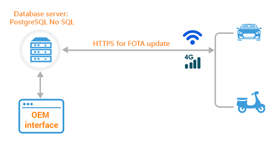
Data flow diagram for FOTA update solution

  2. Integration of Vehicle Pre-Conditions:Certain pre-conditions for vehicle have been integrated, as per the project requirements. These pre-conditions need to be fulfilled, in order to initiate the new FOTA updateThe following are the details of the pre-conditions:
    1. Whenever the user is planning to download the latest version of FOTA packet , released by the OTA update solution provider, one need to ensure that:
      • Gear is set to “Parking mode “
      • The Battery charge level > 50%
      • Vehicle speed = 0 kmph
    2. The infotainment device should have a reliable WiFi/GSM connection to receive regular updates.
  3. Image Security & Device Authentication:
    1. Tight coupling of Build Server Environment (BE) with the Infotainment OS : This ensures that the target end-user device is updated by firmware images , sent by only an authenticated FOTA server.
    2. Device Authentication has been done using SSL certificate Authentication. The device SSL certificate gets verified at every boot session.
    3. Each FOTA image is encrypted using AES-128 encryption standards.

Embitel’s Impact:

  1. With integration of FOTA with the Infotainment System, our customers (the Electric Vehicle Start-ups) are now able to remotely & efficiently management the application software.
  2. The FOTA solution developed by Embitel team consisted of various reusable components, including the FOTA software stack, the cloud framework etc. This translated into development time and cost savings for the customers.

Tool and Technologies:

  • MQTT Protocol: For command exchanges between the cloud server and the infotainment devices.
  • HTTPS : To send secure OTA update to the target end-user device ( Infotainment)
  • PostgressSQL NOSQL: database server
  • Android 7.0 OS


  • 0

[Video] How Different ECU Reprogramming Use-Cases Influence Design of Your Humble Flash Bootloader

Category : Embedded Blog

Similar to the software installed on a PC or a smartphone, automotive ECU applications also require regular software updates.

For instance, an OEM or the product Supplier, want to release a new software version of the existing product line. This new version may contain bug-fixes and some optimizations.

In that case, Automotive ECU Reprogramming becomes a necessity.

Flash Bootloader, a small piece of software installed inside the vehicle control units, is tasked with this ECU reprogramming duties.

As the automotive applications has become advanced, a standard Bootloader is not capable in managing some complex use-cases of ECU reprogramming.

And this has paved the way for the design of different variants of Bootloader. You can also read our detailed blog on types of Flash Bootloaders.

Our latest video on Bootloader delves deep into the need for new Bootloader types and also introduces these variants.

This video on Flash Bootloader will Throw Some Light On:

  • Evolution of Bootloader
  • Need for different variants of Bootloader
  • Different types of Bootloader used for ECU Reprogramming

We will now stop the talking and let the video take over.

This video will be useful for automotive engineers, Business Managers and decision makers (Automotive OEMs and suppliers).


  • 0

What are Different types of Flash Bootloaders that facilitate Automotive ECU (Electronic Control Unit) Reprogramming

Category : Embedded Blog

For our readers who would like to get introduced to the concept of Flash Bootloaders in Automotive, we would recommend you to read this blog- Understanding what is a Flash Bootloader and the Nuances of an Automotive ECU Reprogramming

When Automotive Electronics was in its nascent stage, software engineers had not fully utilized the capabilities of a Flash Bootloader software.

The Embedded Software Engineers, during Automotive Product Development, were more focused on the features and functions of the software.

The need for firmware or application update was not mission-critical, due to not-so-complex features and systems.

Fast-forward to the era of Connected Cars, Infotainment, ADAS and Telematics applications, and the need for frequent software updates can’t be understated. And who empowers these software updates? It is your modest Flash Bootloader Software!

The complexity of the automotive applications has also meant that one type of Flash Bootloader solution is not the best fit for all the business use-cases.

Chances of memory corruption and security threats has paved the way for development of flash bootloader solutions that differ based on their technology architecture, security measures and connectivity features.

Before we discuss these special types of flash Bootloader, let’s first establish their need in the context of changing automotive electronics landscape. Every scenario will be followed up by the type of Bootloader, which is designed to mitigate the mentioned challenge.

Why Use Different Types of Bootloaders? The Scenarios and the Solutions

Reprogramming of the Control Units Software can get tricky at times.

The software image (file that contains the updated version) may be large in size, or there may be a chance of flash drive corrupting the memory.  There is also a possibility that the communication channel may not be secure enough, to support the re-programming.

We will shed lights on all these scenarios and issues that required flash bootloaders to be developed specifically to address them. Let’s find out one scenario at a time!

Scenario 1: An Instance of Memory Corruption by the Flash Driver

The Flash Bootloader comprises of several device drivers and software modules for flashing the Automotive Control Unit. One of them is flash driver.

These drivers act as a liaison between the memory location and the external tool for ECU flashing.

Due to certain malfunctions, the flash drivers can corrupt the memory locations of the Flash Bootloader.

If such a scenario arises, the automotive control unit may not accept the updates or run into other troubles. After all, the Bootloader is the first module to run, when ignition is turned on.

One of the major reasons to consider this scenario while designing the Flash Bootloader is the need for compliance with ISO 26262 Standard for functional safety.

In order to comply with ASIL B and above, your automotive ECU Bootloader should be designed in a way that the issue of memory corruption is completely mitigated.

Solution: A Bootloader with External Flash Driver

The solution for this issue is to ensure that your Flash Bootloader design doesn’t have an integrated Flash driver.

Instead, the flash driver is loaded inside the Flash Bootloader, only when the ECU reprogramming command is sent by the external flashing tool.

It implies that at every instance of the ECU flashing, these steps will follow:

  • Request for re-programming comes from the external ECU flashing tool
  • Flash driver (A small binary file) from the external tool gets downloaded to the Bootloader’s RAM
  • Read and Write function is performed by the Bootloader to flash the ECU
  • After the re-programming is completed, the flash driver is deleted from the RAM of the Bootloader

In terms of ASIL compliance, this type of Bootloader can be seen as a safety mechanism put in place to avoid the hazards of memory corruption and the risks associated with it.

Interestingly, such mechanism does not lead to any substantial increase in the cost of the Bootloader.

Also, there isn’t any substantial increase in the Bootloader development time.

However, the factor that needs to be considered here is the compatibility of the microcontroller platform with the external flash driver. If certain Microcontroller does not support the flash driver, then your team may need to write some additional drivers.

The ECU flashing time, on the other hand, is rather improved. This is because the code that is usually executed from the flash memory (in a standard Bootloader), is now being triggered by the RAM, which is faster.

Scenario 2: Security Threats in ECU Reprogramming

The external ECU flashing tool communicates with the Bootloader over CAN bus. Hence, it is highly likely that the communication can be hacked and the entire ECU be re-produced.

Some more serious security threats can be:

  • Alteration of the firmware image that is being updated
  • Reverse engineering of the firmware
  • Loading of the unauthorized firmware version in the ECU

Not only the vehicle can malfunction due to this, but serious implications can follow and the reputation of the OEM may get adversely affected.

One of the most feasible way of mitigating such risk is to deploy security checks before the software update file is sent to the Bootloader.

Such safety mechanisms also help in making a Bootloader comply with ISO 26262 mandated Automotive Safety and Integrity Level (ASIL).

Solution:  Encryption-Decryption Enabled Bootloader

Here, the idea is to encrypt the software update file before transmitting to the Bootloader via CAN. The encryption will be performed by the ECU flashing tool.

Once the Bootloader receives the encrypted file, the decryption algorithm will kick in. Post the decryption, the regular sequence of ECU flashing will be performed.

These bootloaders are based on Cryptographic algorithms. They serve the dual purpose of protecting the privacy of the firmware update file and verifying the code integrity.

There is a 2-layer security measure deployed in the Bootloader for the purpose, which is explained as follows:

  1. Encryption-Decryption Algorithm: The encryption algorithm resides in the flashing tool and the decryption algorithm sits in the Bootloader Application. This algorithm may be symmetric or asymmetric, depending on the level of security required.
  2. Symmetric algorithm deploys the same key for both encrypting and decrypting the message, while asymmetric algorithm uses public and private keys. In both cases, these algorithms are quite robust and tough to hack.

  3. Protocol-level Security Measures: Security threats such as firmware alteration (downgrading), encryption key alteration, upgrade interruption etc. are not handled by the encrypt-decryption algorithms. Protocol-level measures are required to handle them efficiently.

    To ensure the correct and complete packet has been received by the Bootloader, packet fields are checked at the protocol-level and matched with the packet received by the Bootloader.

    If there is any discrepancy, the packet is not accepted and connection is aborted.

Scenario 3: Flash Bootloader Application Update

So far in the blog, we have discussed only about the ECU application update using the Bootloader. However, the Bootloader application may itself require some software update time to time.

There may be a bug-fixes in the new release of the Bootloader Software or new features may have to be added. The Bootloader software block is tasked with the upgrade of the application block only and there is no provision for it to upgrade itself.

To enable such updates, we need Flash Bootloaders with a defined functionality that can update the Bootloader Application.

Solution: Bootloaders with Primary and Secondary Blocks

These specialized Bootloader solutions have a separate block for the purpose called the secondary block. The role of secondary Bootloader is limited to updating the Bootloader application.

Following is the sequence of Flash Bootloader Application update:

  • The external Flash Tool for the ECU (electronic control unit) sends an update command to the Bootloader; Primary Bootloader receives it
  • If the update is for the Bootloader application, the control is shifted to Secondary Bootloader
  • The Secondary Bootloader erases the primary Bootloader and writes the new firmware package
  • New application is verified and control is again shifted to the Primary Bootloader

Scenario 4: Remote Firmware Upgrade

There are more than several hundreds of ECU applications, which run inside the vehicle. Imagine taking the vehicle to the service station for updating all such applications. It will be a nightmare for the customers and even for the OEMs.

They will need to increase the number of service stations and also add more people to their workforce. So what’s the solution?

Solution: Bootloader with Firmware Over-The-Air Update (FOTA)

A Bootloader with the capability to receive firmware over the Ethernet. Such bootloaders are equipped with a FOTA module that receives, verifies and execute the update over the air.

To learn more about how a FOTA Solution works, please refer to this blog “Understanding FOTA in the Times of ‘Connected Cars’

Scenario 5: Automotive ECU Application gets corrupted

At ignition, the Bootloader checks the integrity of the control unit application using the Check-sum calculation and other methods.

If any discrepancy is found, the application is not run and the process is aborted. For critical applications such as Electronic Stability Program or ABS, failure of application execution can cause serious malfunctions.

A smart Bootloader can help to mitigate such critical issues. Let’s see how.

Solution: Bootloader with a Golden Image (Clone Image)

There is a golden or clone image of the application stored in the Bootloader, as an auxiliary application block.

If an issue is found in the existing application, the Bootloader shifts the control to the clone image of the software and the application need not be aborted. For critical applications, such Bootloader is a life-safer.

And Finally, the Standard Bootloader!

When such scenarios need not be taken into picture, our good old Flash Bootloader fits the bill easily. This standard Bootloader consists of the Bootloader Block and the Application Block.

Upon each ignition, the control will shift to the Flash Bootloader block and it will check for an update. If no update is found, the control will move to the application block.

If the update package is available, the Flash Bootloader will erase the application block, read and write the new software package and verify the application. If everything is good, the control will shift to application block.

Conclusion

Apart from these Flash Bootloader types, other variants may also be developed. Technology architecture of two variants can also be combined to create a third variant. For instance, a flash Bootloader software may have both encryption-decryption capabilities and FOTA capabilities. Likewise, Flash Bootloaders with other hybrid architectures can also be designed, depending on your business use-case.