×

Happy to Help!

This website doesn't store cookies. Enjoy the experience, without worrying about your data!

Great, thanks!

Monthly Archives: April 2024

  • 0

Driving Global Growth with B2B Digital Commerce Innovations


About The Customer:

Our customer is a leading supplier of tobacco with a diverse portfolio of products catering to different regional and consumer preferences.

Business Challenge:

The customer group recognized the need to establish a robust B2B presence in the South Korean market to effectively sell its products online to its outlets.

Developing an e-commerce platform tailored to the B2B segment posed several challenges, including accommodating complex ordering processes and catering to the unique needs of business customers.

  1. Technical Challenges in Flexibility, Reliability & Scalability:
  2. The need of the hour was a robust digital platform that offered flexibility to adapt to evolving business requirements, reliability to ensure uninterrupted operations, and scalability to support rapid business growth. Achieving this trifecta of technical capabilities was a significant challenge given the complexity of the project.

  3. Integration Complexity:
  4. Integrating the new e-commerce platform with their existing systems, including SAP/TAO, Swift+, and OMS, presented a formidable challenge. Ensuring seamless communication and data synchronization among these diverse systems was crucial for the success of the project.

  5. Adopting MACH Architecture Principles:
  6. The customer brand sought a modern solution built on Cloud, API, and Microservices-first principles (MACH architecture) . Implementing these principles required expertise and careful planning to architect the platform effectively.

  7. Phased Development Approach:
  8. To accommodate the evolving needs of the business and ensure scalability post-MVP, the customer required a phased development approach. Developing the platform in stages while maintaining coherence and scalability presented its own set of challenges, including managing dependencies and prioritizing features.

  9. Security & Performance Testing:
  10. Ensuring the security and performance of the platform was paramount for the customer . With huge volume of highly sensitive business data and transactions flowing through the system, rigorous security testing and performance optimization to safeguard against potential threats became a critical requirement.


Embitel Solution:

Embitel was  onboarded by the global brand to develop a state-of-the-art B2B e-commerce platform tailored to the unique requirements of the South Korean market.

A strong team of 20+ digital experts consisting of chief solution architects, certified business analysts, Magento experts, Node JS developers, DevOps head, and QA lead was soon formed to develop the custom solution for our customer in fast-track mode.

Leveraging our extensive experience in delivering complex solutions, along with our strong relationships with globally renowned associates of our customers, we have successfully tackled the following challenges:

  • Flexible, Reliable, and Scalable Architecture: Designed and implemented a flexible, reliable, and scalable architecture that met our customer’s technical requirements, to ensure adaptability to changing business needs and to support exponential growth.
  • Complex System Integrations: Seamlessly integrated the new online platform with brands’ existing systems, including SAP/TAO, Swift+, OMS, and over 40 other integrations, ensuring smooth data flow and interoperability between systems.
  • MACH Architecture Implementation: Built the platform based on Cloud, API, and Microservices-first principles (MACH architecture), providing high scalability, flexibility, sustainability, and cost-effectiveness.
  • Phased Development: Adopted a phased development approach, allowing the platform to be developed incrementally while ensuring scalability and readiness for post-MVP requirements.
  • Security & Performance Testing: Conducted thorough security testing and performance optimization to ensure the platform’s security and deliver optimal performance under varying loads.
    In addition to the above, here is a quick snapshot of the key features integrated with the solution:
  • Exclusive Priority Based Promotions & Messaging
  • B2B Promotions Based on the Volume of the Order
  • Access-based management of Bulk Orders Multi-Store Owners
  • Streamlined Stock Returns with Account Closure

The resulting platform empowered our customer brand to establish a strong B2B presence in the South Korean market, providing a seamless and efficient online sales channel for its outlets while paving the way for future growth and innovation.
 

The Embitel Impact:

  1. Foundation for Global Expansion:
  2. By developing a scalable B2B E-commerce platform tailored for the South Korean region, Embitel has provided the customer group with a solid foundation that can be extended to other geographies, accelerating its global growth strategy.

  3. Phased Scalability:
  4. The phased development approach implemented by Embitel enables the platform to scale seamlessly to meet post-MVP phase requirements. This means as the business grows and evolves, the platform can easily accommodate additional features, integrations, and functionalities without compromising performance or stability.

  5. Seamless Buying Experience in New Market :
  6. The new B2B E-commerce platform enhances the overall customer experience of the customer’s outlets in the new markets. With streamlined order management, intuitive user interface, and personalized features, their outlets can enjoy a seamless and efficient buying process, leading to increased satisfaction and loyalty.

  7. Accelerated Time-to-Market:
  8. Through efficient project timeline management and phased development, Embitel ensured the customer could quickly launch its platform, accelerating their digital transformation journey.

Tools & Technologies:

  • Adobe Commerce on Cloud : Ecommerce platform
  • Magento PWA along with  React + NextJS : Custom Front End for B2B web shop

  • 0

Power Converter Topologies for Electric Charging Stations

Category : Embedded Blog

With the surge in demand for electric vehicles, the race is on to develop cutting-edge, energy-efficient charging infrastructure that can power up our vehicles quicker than ever before. Gone are the days of fretting over battery capacity and range anxiety; the automotive industry is witnessing a monumental shift, all thanks to relentless innovation in the EV sector.

Enter fast DC charging—a game-changing solution poised to revolutionize the EV landscape. In this article, we’ll delve deeper into the realm of power electronics applications within EV charging stations, shining the spotlight on various electrifying topologies that are propelling us towards a greener tomorrow.

Before going deep into power electronic topologies, we will first know more about the charging infrastructure for electric vehicle. A charging station, also known as Electric Vehicle Supply Equipment (EVSE) or Charging point is a part of Grid infrastructure and used for supplying electrical power to plug-in electric vehicles for charging battery packs.

The charging stations can be installed in public places like on the street side, at government facilities and retail shopping centres/malls, or can be seen in isolated areas like residences, hotels, and workplaces.

Understanding the Different Types of EV Chargers

Electric vehicle batteries can only be charged by DC power supply, but the main electricity that gets delivered from the power grid is AC. Therefore, all electric vehicles require AC-to-DC converter for charging the battery.

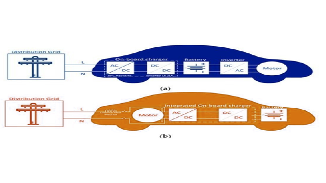
Electric vehicle battery chargers fall into two categories: off-board and on-board, and they can have either unidirectional or bidirectional power flow capability.

  • In an AC charging station, AC supply from power grid is supplied to electric vehicle batteries through the vehicle’s On-board charger which converts AC into DC power. These onboard chargers are present inside the electric vehicle and are designed for lower kilowatts of power transfer. AC charging stations are slow charging stations and are the most widely used charging method.
  • In DC charging stations, the AC to DC converter is present outside the electric vehicle and are known as Off board chargers. These DC chargers provide higher power charging by placing the converter inside the charging station instead of the vehicle to avoid size and weight restrictions which can increase the vehicle’s overall efficiency. The station directly provides DC power to the vehicle, bypassing the converter installed onboard.

The onboard and off-board chargers for a Plug-in electric vehicle are illustrated below.

Choosing the Right EV Chargers

It is important to understand different types of EV chargers available in the market which are used in AC and DC charging stations. These EV chargers are classified based on power levels, battery charging time and their application. There are three main types of EV chargers: Level 1, Level 2, and DC Fast Chargers.

Parameters L1 Charger L2 Charger DC Charger
Charging station AC AC DC
Voltage source (V) 120/230 VAC, single phase 208-240 VAC, polyphase 300-600 VDC
Charging Current (A) 12-16 15-80 400
Charging time (Hrs) 12-17 6-8 0.5-1
Speed Slow Semi fast Faster
Type Onboard charger Onboard charger Off board charger
Location Residential Residential/ Commercial Commercial

Each EV charger has its own advantages and disadvantages. It is important to consider crucial factors like charging needs, vehicle compatibility and power output of electric vehicles before selecting right kind of charger. L1 and L2 chargers are suitable for short commute and daily usage whereas DC fast chargers are ideal for long trips and quick top up of batteries.

L1 chargers are slow but can be plugged into any standard outlet. Level 2 chargers are the popular choice for home charging and take less time than L1 chargers.

Check out our blog on EV charging for more information on home charging and public charging.

Role of Power Electronics in Battery Charging System

Power electronic converters play a vital role in battery charging systems. It controls the charging process and manage power flow when the vehicle is connected to a charging station. DC charging stations require high power modular converters which are capable of fast charging.

Few important characteristics of power converters in battery charging system are their energy density, efficiency, and capacity to regulate voltage and current as per battery requirement.

Power Converter Topologies for DC Fast Charging

Typically, an EV battery charger consists of two stages of conversion. One is AC-DC conversion stage for rectification of incoming AC power from Grid into DC power required and guarantees unity power factor.

Second one is DC-DC conversion in which DC voltage is stepped up or stepped down to match the specific requirements of batteries. This voltage varies as per the state of charge (SoC) of battery pack.

Let us first see the different types of power converter topologies used for DC Charging stations and then for AC charging stations.

AC-DC Power Converter

The first level of power conversion in EV charging station is AC-DC power conversion, which is also known as PFC (Power factor correction) stage. AC-DC power converter converts the incoming AC voltage of 380-415 V into stable DC link voltage of 1000 V.

With the presence of filter, a phase shift between the sinusoidal AC power supply voltage and current can happen and the power factor (PF) drops. A power factor correction (PFC) circuit reduces the harmonic distortion in the supply current and creates a current waveform close to a fundamental sine wave to increase the power factor to unity.

Thus, PFC stage helps in maintaining sinusoidal input current to give controlled DC output voltage. Power factor correction helps in increasing power efficiency under the same input conditions.

PFC topologies are of three types – passive, hybrid, and active PFC rectifiers. Depending on power level, it is of two types – single phase and three phase PFC converters.

For fast charging application, high efficiency and smaller size, the most suitable PFC topologies in an EV charging station are three phase active PFC rectifiers which can be used for high power level above 3.3 kW. A boost chopper is a basic topology of any active PFC topology. Three phase active PFC rectifiers are of different types – two level PFC, Neutral point clamped (NPC) PFC and Vienna PFC.

AC slow charging
  • A three phase two level PFC rectifier supports bidirectional power flow operation and generates low total harmonic current distortion with a power factor close to unity. It consists of a bridge rectifier with six controlled switches. It provides good efficiency and easy control but are bulky in size due to filter inductors which are required for regulating THD level.
  • Neutral point clamped PFC rectifier is another type of PFC rectifier which uses the Neutral Point Clamp scheme commonly found in inverter circuits. It consists of a bridge rectifier with twelve controlled switches and six diodes. It has higher efficiency (low power loss) due to adoption of multi-level scheme. This topology also has a bipolar DC bus which helps in increasing power levels by connecting two DC-DC converters in either series-series or series-parallel configuration. The major drawback of this converter is the number of semiconductor switches which make the circuit costly, bulky & complex.
  • The Vienna PFC rectifier is more popular than the other rectifiers as it provides power factor close to unity and low total harmonic distortion. It has less complex circuit due to reduced number of controlled switches and has high power density as it requires only half of the inductance for the boost inductors. Its only drawback is that it only supports unidirectional mode power transfer from the grid to the DC side.

Among all the three PFC topologies discussed, Vienna PFC is most cost effective and gives quality output voltage and input current whereas NPC PFC is best suited for high power density and bidirectional power flow.

DC-DC Power Converter

The second level of power conversion in EV charging station is DC- DC conversion. The Buck converter is used, as the battery voltage is less than the output voltage of the rectifier. It converts the incoming 800 DC voltage into lower DC voltage depending on the State of Charge (SoC) of the battery while ensuring safe operation by communicating with the BMS. DC-DC converter can deliver wide range of voltage (50-500V) at rated power to a battery, for example 48 V to a two-wheeler electric bike and upto 500 V to plug-in electric vehicle.

There are two types of DC-DC converters based on the presence of galvanic isolation provided by the power transformer on the grid side: isolated DC-DC converter and non-isolated DC-DC converter. If the galvanic isolation is present on the power transformer, then non isolated DC-DC converter is used, otherwise isolated DC-DC converter can be used.

  • Three-phase interleaved DC-DC converter – The three-phase interleaved DC-DC buck converter is a type of non-isolated DC-DC converter which can be used for decreasing the input voltage and high current application with lower size inductor filters.
  • Three-phase interleaved DC-DC converter – If bidirectional flow is required between grid and electric vehicle power storage, a three-phase interleaved DC-DC buck-boost converter can be used in charging stations.

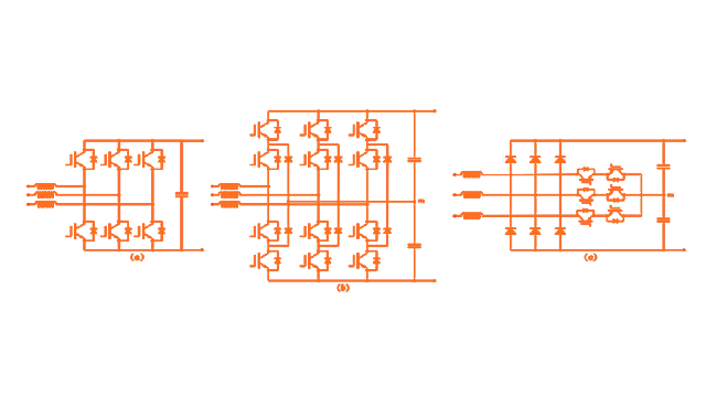
If no galvanic isolation is provided on the grid side, a transformer is provided along with DC-DC converter for galvanic isolation and operational safety. The most popular isolated DC-DC buck converters are Phase shift full bridge (PSFB) converter and Dual active bridge (DAB) converter.

  • The phase shift full bridge DC-DC converter (figure a) consists of a transformer for isolation and has primary and secondary side. Its primary side consists of an H bridge with controlled switches and secondary side consists of H bridge with diodes which are connected to batteries. This converter can be used only for unidirectional power flow but can deliver high output voltage and power rating with good efficiency. Both Zero current switching (ZCS) and Zero voltage switching (ZVS) can be performed in this converter.
  • For bidirectional power flow a Dual active bridge DC-DC converter (figure b) can be used in place of a PSFB DC-DC converter for EV charging stations. The major difference is that on secondary side, diode bridge is replaced by H Bridge controlled switches which helps in bidirectional power flow. The disadvantage of this topology is the complex circuit due to control of eight power switches and non-resonant operation which results in less efficiency at low power rating.

Power Converter Topologies for AC Fast Charging

AC charging typically needs an on-board AC-DC power converter. Interestingly, both the motor and the motor drive inverter serve dual purpose. They not only convert DC power from the battery into AC power for the motor but also function as the on-board charger for the battery. This integration removes the necessity for a distinct AC-DC power converter dedicated to the on-board charger.

AC

An integrated on-board EV charger is a bidirectional EV charger that operates in all EV operation modes using a single inverter/rectifier. The EV traction/propulsion, braking, and battery recharging all utilize the same power switches, which allows for a reduction in the number of power electronic devices.

In this way, the EV charger’s price, dimensions, and weight are significantly decreased. Recently, this technology has come to light as an ideal solution between off-board and on-board battery chargers.
 

Batter charge
 

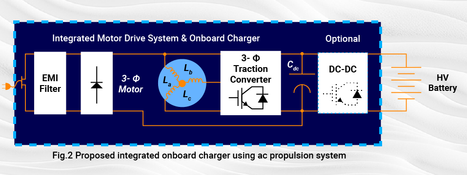
During propulsion, the battery provides the propulsion power through a three-phase traction converter (inverter mode) and the additional diode bridge has no influence on the traction converter operation. While the battery is in charging mode, the grid AC line voltage is rectified by the diode-bridge and the propulsion machine windings while the traction converter develop a two-channel interleaved boost converter, which is utilized for PFC and output voltage/current regulation.

In order for this method to be effective, it must fulfill specific technical criteria throughout the charging procedure, including minimal or no alteration to winding configurations and maintaining an average torque of zero.

Conclusion

This article is a useful guide that provides a comprehensive overview of EV chargers and types of power converter topologies used inside the EV for fast charging. The selection criteria for EV chargers depend upon efficiency, durability, performance, and cost. With the increase in charging power demand for different levels and evolution of the vehicle electrical system, new types of DC and AC chargers are emerging. These types of chargers provide high power and have a compact architecture and low cost.


  • -

The Critical Role of Safety Mechanisms in ISO 26262 Compliance

Category : Embedded Blog

The fusion of innovation and safety dictates the pace of progress in the automotive realm. While innovation is largely brought about by enhancing the electronic systems in a vehicle, safety concerns come as a by-product. And that’s where ISO 26262 standard comes into the picture- to ensure that functional safety is not left behind in the race to automation and connectivity.

As we delve into the world of modern vehicles, we encounter an array of sophisticated features, from autonomous driving capabilities to interconnected infotainment systems.

The importance of ISO 26262’s safety mechanisms becomes increasingly apparent in this context. They serve as the foundation upon which the future of automotive reliability and passenger safety is built.

For instance, in advanced driver-assistance systems (ADAS), safety mechanisms play a pivotal role in maintaining operational integrity, even in the face of component failures.

Consider a vehicle equipped with level 3 autonomy, where multiple sensors and cameras are employed to perceive the vehicle’s environment. This system integrates redundancy for critical sensors, ensuring that if one fails, another can take over seamlessly, allowing the vehicle to continue its journey safely.

Furthermore, sophisticated watchdog timers, another set of safety mechanism, monitor the system’s performance, ready to initiate a safe mode if anomalies are detected.

How do ISO 26262 Experts Derive Safety Mechanism?

The derivation of safety mechanisms is intrinsically linked to the ISO 26262 safety lifecycle. It outlines a comprehensive approach to managing functional safety throughout the development of automotive systems.

This lifecycle is segmented into phases that span from the conceptual inception of a product through to its decommissioning, ensuring that safety considerations are integrated at every stage.

Within this framework, safety mechanisms are most prominently conceptualized, designed, and verified during specific phases of the lifecycle.

Safety mechanism life cycle

Here’s how they relate:

  • Concept Phase (Part 3 of ISO 26262): The journey begins with the Concept Phase, where the initial Hazard Analysis and Risk Assessment (HARA) is conducted. This phase sets the foundation for safety by identifying potential hazards and defining the safety goals, laying the groundwork for the subsequent derivation of safety mechanisms to mitigate these risks.
  • Product Development: System Level (Part 4 of ISO 26262): Moving into Product Development at the System Level, the functional safety requirements are specified based on the safety goals identified earlier. It is in this phase that the Functional Safety Concept is developed, detailing how each safety goal will be achieved through specific safety mechanisms.

    This marks the phase where safety mechanisms are directly derived and elaborated upon. A critical bridge between abstract safety goals and their practical implementation is thus formed.

  • Product Development: Hardware and Software Level (Parts 5 & 6 of ISO 26262): As the lifecycle progresses to the Product Development at the Hardware Level and Software Level, the technical safety requirements become the focus.

    Here, the safety mechanisms identified in the system level are further refined and integrated into the hardware and software design. This includes the development of redundant architectures, error detection and correction protocols, and other mechanisms tailored to mitigate identified risks.

What are the Typical Safety Mechanisms Deployed in ISO 26262 Compliant Automotive Solutions?

Challenges faced in ensuring functional safety for automotive solutions are unique for each project. Safety mechanisms vary accordingly. Operating conditions, ASIL rating etc. dictate the kind of safety mechanism needed to be deployed. Another important factor about implementing safety mechanisms is the level at which they must be deployed. Let’s understand this aspect in more detail:

Hardware Safety Mechanisms

  • Redundancy: This involves duplicating critical components or systems so that if one fails, the other can take over. Redundancy is vital for functions like braking and steering, where failure could lead to catastrophic outcomes. For instance, modern vehicles might have multiple brake circuits, ensuring that if one circuit fails, the vehicle can still be brought to a stop safely.
  • Watchdog Timers: These are used to monitor the system’s operation and ensure that it is functioning within expected parameters. If a software or hardware component becomes unresponsive, the watchdog timer can reset the system or put it into a safe state. This mechanism is crucial for preventing system lock-ups that could lead to loss of control.
  • Error Detection and Correction (EDAC) Codes: EDAC codes, such as Parity Bits and Error Correction Codes (ECC), are used in memory and communication systems to detect and correct errors automatically. They help maintain data integrity, ensuring that even if data gets corrupted during transmission or storage, the system can identify and rectify the errors, preventing malfunction or data loss.
  • Safe Shutdown Circuits: These circuits ensure that, in the event of a failure, the system can be safely powered down without causing additional hazards. For example, if a fault is detected that could lead to overheating or fire, safe shutdown circuits can disconnect power sources, preventing further damage.

Software Safety Mechanisms

  • Error Handling and Recovery: Software is designed to detect errors and either correct them or enter a safe state. This could include mechanisms for retrying operations, using backup data, or switching to a reduced functionality mode that maintains critical operations while minimizing risk.
  • Safe State Management: In the event of a detected fault, systems need to transition to a “safe state” where no harm can occur. This might mean disabling certain functions, engaging emergency brakes, or moving to a minimal operational mode until the issue can be addressed.
  • Redundancy and Diversity: Similar to hardware, software redundancy involves having multiple software components that can perform the same function, so if one fails, another can take over. Diversity means having these redundant components developed using different methods or algorithms to reduce the risk of a common cause failure affecting all components simultaneously.
  • Safety Interlocks: These are checks or conditions that must be met before certain operations can proceed. For example, a vehicle might prevent the engagement of the autonomous driving mode unless all required sensors are operational, or it might not start if the driver’s seatbelt is not fastened.
  • Runtime Monitoring: Software routines continuously monitor the operation of both hardware and software components during runtime. This can include checking for out-of-range values, unexpected states, or the integrity of communication between components, triggering corrective actions if necessary.

Integrating Robust Safety Mechanisms in ISO 26262 Compliant Motor Control Development

To get a better understanding of how safety mechanisms work to mitigate functional safety hazards, let’s consider an example of motor control solutions. The application of motor controller in the vehicle decides its safety criticality. The more advanced use-cases include electronic steering control, ABS, etc, and they are mostly assigned ASIL D, the most stringent ASIL rating.

The adaptation of safety mechanisms into the development process of motor control solutions can be understood through a structured framework, encompassing system design, hardware considerations, and software strategies.

Safety Mechanisms for Motor Controller at System Design Level

  • Embracing Redundancy: A motor control unit that controls a vehicle function such as electronic power steering cannot afford to lose its function. Implementing redundancy within a motor control system means designing the system with backup pathways that can seamlessly take over in the event of a failure, ensuring that there is no loss of functionality.

    Imagine a vehicle equipped with an electric power steering system, which is crucial for the driver’s ability to control the vehicle. For redundancy, the system could be designed with two motor control units (MCUs) operating in parallel.

    Each MCU independently receives input from the vehicle’s steering sensor but only one MCU actively controls the steering motor under normal conditions. If the primary MCU fails, the secondary MCU immediately takes over, ensuring that the steering function remains unaffected.

  • Implement Watchdog Timers: The motor control ECU must be incorporated with watchdog timers. These timers can reset the motor control system or trigger a safe mode operation if the system becomes unresponsive. Such an arrangement ensures that “software freezes” do not lead to hazardous situations.

    Let’s continue with the earlier example of an electronic steering control. Under normal operation, the system’s software resets the watchdog timer at regular intervals, well within the timer’s countdown.

    However, if there’s a software issue that causes the control loop to freeze or run too long, the watchdog timer would reach zero. Recognizing this ‘failure to reset’ as a sign of system unresponsiveness, the watchdog timer then triggers a predefined response.

    It could instruct the system to enter a safe mode, where the steering assistance is reduced or turned off in a controlled manner, alerting the driver through dashboard indicators that manual steering is required.

  • Design for Overcurrent and Overvoltage Protection: Should the motor control system experience an overcurrent condition due to a short circuit, an overcurrent protection circuit would cut off power to the motor to prevent damage.

    Similarly, overvoltage protection safeguards the system against voltage spikes that could harm electronic components.

  • Secure Data Communications: To ensure secure firmware updates to the motor control system, encrypted communication channels are used. This prevents unauthorized modifications, ensuring that only verified and secure firmware versions are installed.

Safety Mechanisms for Motor Controller at Hardware Level

Safety mechanisms at hardware level have special importance in ISO 26262 compliance. Hardware serves as the foundational layer of defense against risks and associated hazards.

Unlike software, which can be updated or patched relatively easily, hardware forms the immutable backbone of system architecture, making its initial design and integration of safety mechanisms vital for long-term performance and safety.

Here’s a few hardware level safety mechanisms with respect to motor control system:

  • The integration of Built-in Self-Test (BIST) features within the hardware layer underscores a proactive approach to safety. This enables regular diagnostic checks that support early fault detection and system reliability.
  • Error Correction Codes (ECC) emerge as heroes in maintaining data integrity, adept at identifying and correcting errors. Such errors, if go undetected, could mar memory and data transmission.
  • The role of Safe Shutdown Circuits is of utmost importance as they ensure that even in the face of unexpected power losses or faults, the system can power down safely. Such safety mechanism helps in avoiding data corruption and hardware damage.
  • Isolation barriers serve as crucial fortifications, segregating parts of the system to prevent the spread of electrical faults, thereby minimizing the risk of cascading failures.
  • Monitoring of temperature and voltage plays a pivotal role in preempting potential hazards, enabling timely interventions that prevent overheating, voltage spikes, or thermal runaways.
  • The design for Electromagnetic Compatibility (EMC) signifies a commitment to minimizing electromagnetic interference. This ensures the motor control unit’s safe operation amidst electromagnetic interference of all sorts.
Function Potential Failure Modes Corresponding Technical Safety Mechanism
Speed Control Over-speed, Under-speed – PID (Proportional-Integral-Derivative) control adjustments based on real-time speed feedback. Dynamic braking integration for immediate deceleration
Torque Control Excessive torque, Insufficient torque – Real-time torque feedback loop with torque estimation algorithms. Adaptive torque limiting based on operational conditions
Position Control Incorrect positioning, Oscillation – High-resolution encoder feedback for precise position control. Advanced filtering and PID tuning to dampen oscillatory responses
Temperature Monitoring Overheating, Thermal runaway – Direct temperature sensing with thermistors integrated into control algorithms for dynamic thermal management. Activation of external cooling systems based on thresholds
Current Monitoring Overcurrent, Short circuit – Fast-acting current sensing circuits with digital signal processing for immediate response to overcurrent conditions. Programmable current limits with automatic shutdown
Voltage Regulation Overvoltage, Undervoltage – Precision voltage monitoring with ADC (Analog-to-Digital Converter) feedback. Software-controlled power converters for real-time voltage adjustment
Communication Data corruption, Loss of communication – CRC (Cyclic Redundancy Check) for data integrity verification. Timeouts and automatic retransmission of corrupted or lost packets
Emergency Stop Inability to stop in an emergency – Multi-channel input monitoring for redundancy in emergency stop signals. Immediate execution of predefined safe stop sequences
Power Supply Management Power failure, Unstable power supply – UPS (Uninterruptible Power Supply) integration for critical components. Voltage sag detection with seamless switch-over to backup power
Cybersecurity Unauthorized access, Tampering – Mutual authentication protocols and secure boot mechanisms. Real-time monitoring and anomaly detection to identify and mitigate cybersecurity threats
Packetization Packet loss, Packet corruption – Data fragmentation and reassembly algorithms to ensure complete data transmission. Use of sequence numbers and time-stamping to detect and correct out-of-order or lost packets
Clocking Clock drift, Clock failure – Synchronization protocols like PTP (Precision Time Protocol) for clock alignment. Independent watchdog timers to detect and correct clock discrepancies
System Reset Incomplete reset, Failure to reset – Supervisory microcontroller for monitoring and managing the reset process  Implementation of hardware-based and software-enforced reset sequences

Safety Mechanism for Motor Controller at Software Level

Modern motor control systems have complex algorithms controlling their speed and torque based on the use-case.

These software algorithms enable continuous monitoring of motor operation parameters, such as speed, torque, and temperature.

By analyzing this data in real-time, the software can detect anomalies that may indicate potential safety issues, like overheating or unexpected operational behavior. Upon detection, the system can automatically adjust operational parameters or shut down the motor to prevent damage or accidents.

Let’s look at some of the safety mechanism integrated at software level:

  • Error Detection and Handling: The strategies that identify and correct data discrepancies come under this category of safety mechanism. They ensure smooth system operation even when faced with unexpected anomalies.

    The motor control software uses cyclic redundancy checks (CRC) for detecting errors in data received from sensors. If an error is detected, the system can request the data again or use a default value to maintain operation while marking the sensor data as unreliable.

  • Safe State Transition Management: These are the mechanisms that manage transitions between operational states in a controlled manner, maintaining safety throughout the system’s operation.

    Software controls the motor’s state transitions, such as from acceleration to deceleration, ensuring that these changes occur smoothly and predictably to avoid creating unsafe conditions.

  • Software Redundancy and Diversity: These safety mechanisms include approaches that introduce fault tolerance through parallel modules or diverse software strategies. Such mechanisms aid in mitigating common cause failures and enhancing system robustness.

    For example, two separate software algorithms calculate the required motor torque. If the results differ beyond a predefined threshold, the system flags a potential error and can revert to a conservative operation mode or alert the driver.

  • Safety Interlocks and Checks: These gatekeepers ensure all operations adhere to safety parameters, preventing unsafe conditions. This is achieved by verifying the integrity of inputs and monitoring system variables.

    In the context of a motor controller, before enabling high-speed operation, the motor control system verifies that all safety conditions, such as proper engagement of the vehicle’s transmission and the absence of fault codes, are met.

  • Fault Tolerance and Error Recovery: If a non-critical software module fails, the motor control system can bypass the module, allowing continued operation in a degraded mode until the issue can be addressed.

Conclusion

Looking forward, as automotive technologies continue to evolve, the role of safety mechanisms will only become more critical. Their ongoing development and refinement will be key to addressing the new challenges these technologies present.

Ensuring safety is paramount in automotive innovation. In this evolving landscape, following ISO 26262 guidelines with robust safety mechanisms is more than a regulatory must—it’s a fundamental aspect of automotive progress, showing the industry’s solid commitment to safety.