×

Happy to Help!

This website doesn't store cookies. Enjoy the experience, without worrying about your data!

Great, thanks!

Monthly Archives: January 2023

  • 0

IO CIF Connector for AEM Improves Marketing Agility & Offers Immersive User Experiences

Adobe Experience Manager (AEM) features like the Commerce Integration Framework (CIF) provide an easy path to integrate the platform with ecommerce engines. Accessing ecommerce store data, displaying it, collecting responses from website users, etc. can all be accomplished by the CIF.

With AEM and Commerce integration, website visitors can register and start shopping immediately. They will be able to view price changes instantaneously as well.

The best part is that these additions to AEM help companies deliver personalized and exclusive customer experiences.

IO CIF Connecter from Embitel and Diconium

The Digital Experience teams at Embitel and Diconium have gone a step ahead and developed an IO CIF (Commerce Integration Framework) Connector.

The IO CIF Connector acts as an interface which links the marketer’s AEM repositories with third-party commerce platforms like SAP Commerce and Commercetools. It basically acts as a bridge between the frontend and the backend.

Using the IO CIF Connector, ecommerce enterprises can leverage the maximum benefits of Adobe Experience Manager as it integrates seamlessly within the business workflow.

IO CIF Connector Demo

This demo of the IO CIF Connector shows how it enables marketers to easily enhance the website to offer relevant shopping experiences. In this demo, we see…

  • How marketers are facilitated with IO CIF features which helps them to create better user experiences without complexities.
  • How to increase sales and conversion by providing seamless shopping experiences
  • Making every page shoppable and helping customers add the products into carts from anywhere and any device
  • How to integrate IO CIF Connector with any third-party tool smoothly
  • Detailed explanation of Drag-and-drop features
  • How to bridge the gap between content ad commerce and create exceptional experiences for customers

Why Should You Opt for the IO CIF Connector?

IO CIF Connector is an easy plugin app based on GraphQL. It takes less time to track, requests are processed easily, the robustness of the software is fast. It also accommodates a database of any order and size.

The best thing is it took only 4 developers to fructify this product within 6 months. The results were incredible, the product became easy to handle, better cross-selling options, dynamic, personalized and relevant shopping experience for each customer.

Advantages of IO CIF Connector

  • Customization at every touchpoint for every customer based on their profiles.
  • Drag-and-drop feature helps in creating and distributing eCommerce pages
  • Enhanced content creation and delivery
  • Availability of ‘preview’ option for content before execution on various devices
  • Purchasing process made smooth and easy with the availability of dynamic pages
  • DAM (Digital Asset Management) tool to manage all kinds of assets
  • Efficient cross-selling through automated product manifesto

We discuss in detail in the article below the product developed for our client and its outcomes.

Technical Specifications of IO CIF Connector

IO CIF Connector is primarily used to revamp the data from SAP Hybris/ Commercetools into a functional format by AEM and other Adobe Experience Cloud products.

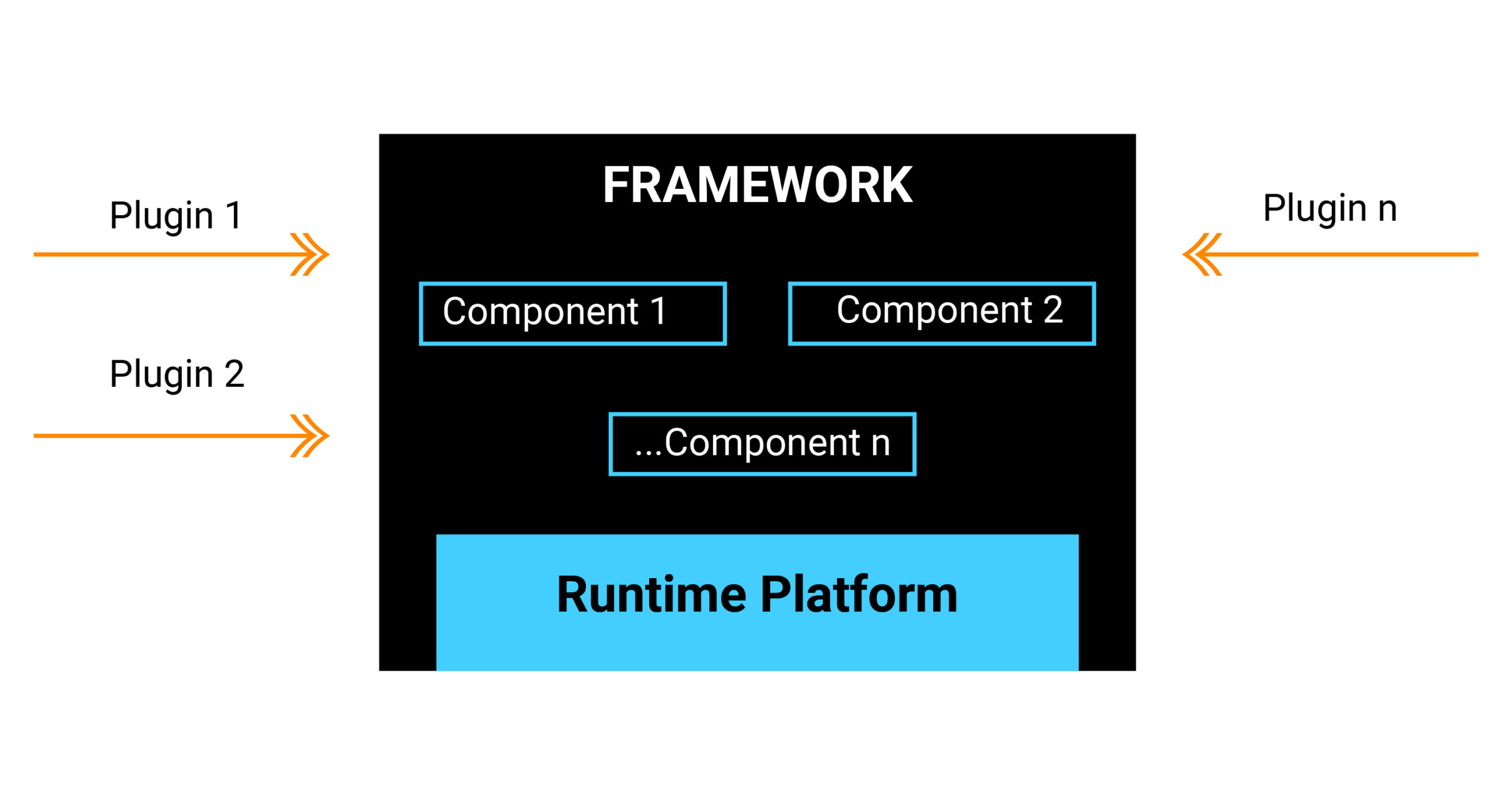
It is based on Adobe I/O and Apache Open-whisk (OW) framework.

The principal constituents of the new commerce services are serverless functions (OW actions). These OW actions get linked with the system or other endpoints through their APIs and can be installed on Adobe I/O Runtime. The actions are performed in response to the events. OW oversees the architecture, servers and scalability.

The AEM and SAP Hybris / Commercetools offer a CDN (Content Delivery Network) for your assets that allows your content-rich pages to load faster. AEM allows you to personalize not only content but also images and video making the entire page worth browsing. Also, just with a single click on the content and instantly you can check the cart for added items.

The product is deployed diligently with Adobe Experience Manager, Adobe’s comprehensive content management system within Adobe Marketing Cloud. SAP Hybris / Commercetools have been upgraded to support Adobe Experience Manager’s new features.

AEM’s newly stated functionalities support dynamic requests and experiences, thereby empowering organizations to quickly and smoothly apply commerce wherever possible and leverage the benefits. The experiences could be related to in-store associate apps, digital signage, mobile and IoT devices, or social commerce to build context-specific transactions.

Customer Success Story

  • Customer sees a remarkable increase in online sales
  • Unified and smooth integration of B2C and B2B commerce platforms
  • Assistance in building a completely digitalized after ‘pre-sales’ process
  • Go Live went earlier and successfully than the scheduled time
  • Roll-out in 4 countries within 3 months of launch
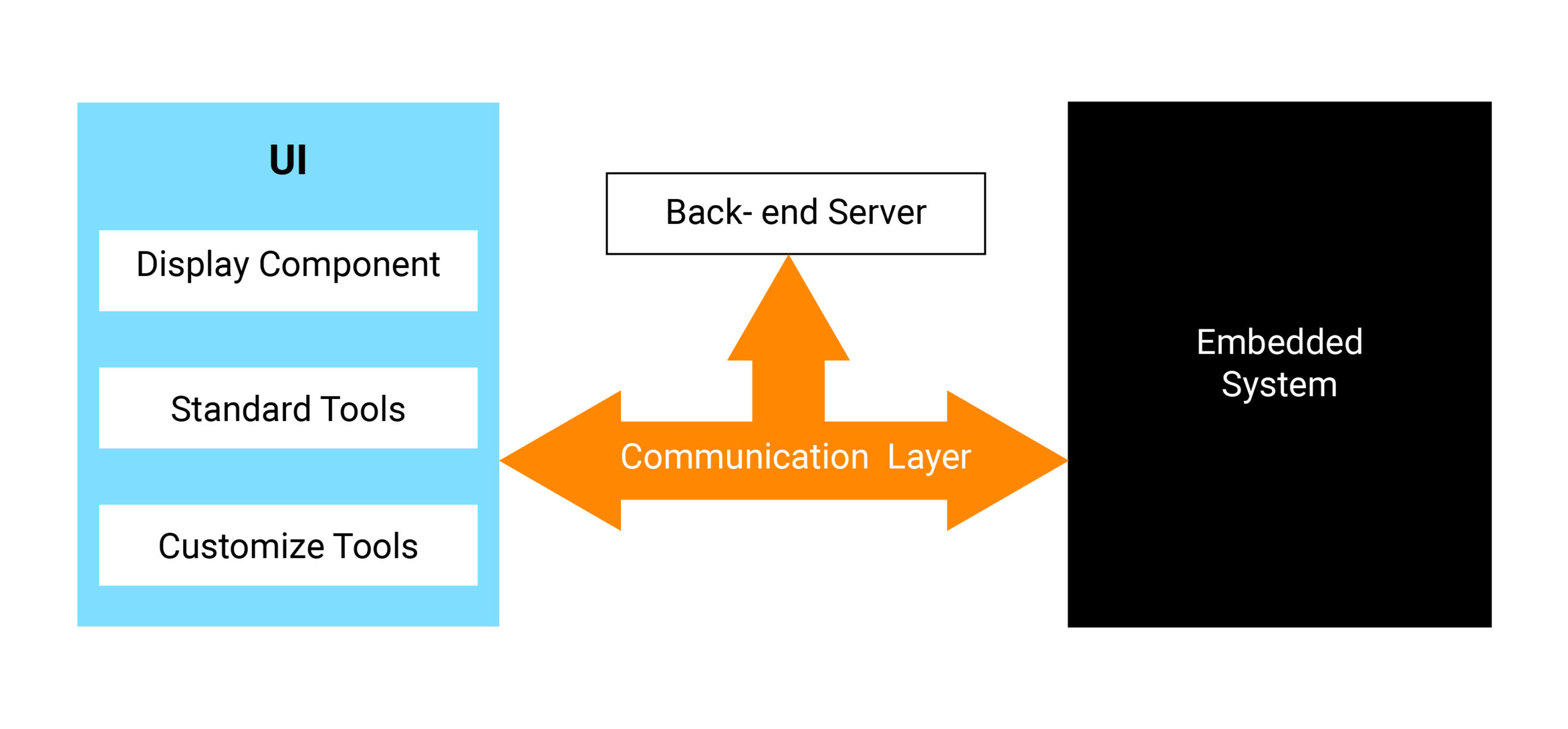
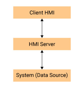
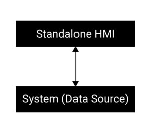
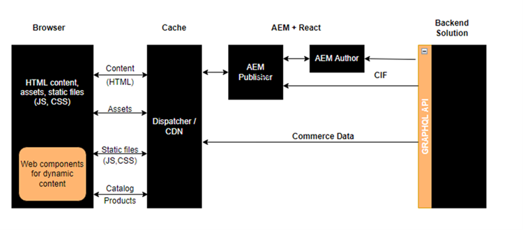
Architecture Design


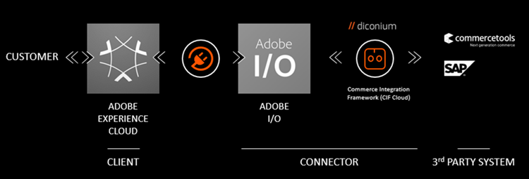
CIF Integration Design

Significant Outcomes of the Project

Delivered customized and immersive shopping experiences at scale.

Simplified assessment and control on building, maintenance and testing of product and experiences.

Easy availability of ready to use elements and IT agility for flexible solution framework.

Conclusion

AEM’s add-ons have been a boon to users, developers and marketers alike. With the addition of IO CIF Connector into the kitty, AEM has empowered customers into creating better customization and nuanced experiences for users everywhere.

The incredible framework of IO CIF Connector helps in any third-party integration happen seamlessly and efficiently. The results so far have been fantastic. Customers across the globe have vouched for unprecedented flexibility with this AEM extension.

IO CIF Connector is definitely a time-saving and economical commerce solution.

We at Embitel provide end-to-end ecommerce solutions to our esteemed clientele globally. Schedule a call with our sales team to find out more: sales@embitel.com


  • 0

Integration of CAN and UDS Stack on Android Automotive OS


About the Customer:

Our customer is a Europe-based Tier-1 supplier of automotive electronics for leading automotive OEMs. They specialize in the development of electronic equipment for passenger, industrial and commercial vehicles.

Business Challenge:

The customer has transportation devices running on Android Automotive OS 8.1. They were working on after-sales maintenance and repair of the devices. In this regard, they wanted to integrate CAN and UDS protocol stacks in their product to expedite vehicle diagnostics functionality.

The customer found that Embitel offers ready-to-deploy CAN and UDS stacks. We also have a capable IoT engineering team with experience developing infotainment system on Android Automotive.

Our automotive and IoT case studies highlighting our past projects compelled them to partner with us for this project.

Embitel Solution:

This was the first time our software stacks were being integrated on Android Automotive platform.

The customer provided us a custom board which was already running on Android 8.1 Automotive OS and also, shared their source code. Their complete work environment credentials were shared as well.

The challenge here was – We had the CAN and UDS stacks developed for MCU environment and we needed to adopt them for the Android based environment. Another challenge was to understand the customer code base and decide on the strategy to integrate the CAN and UDS stacks.

We integrated our proprietary CAN and UDS stacks with the customer’s existing software. We also performed system testing to validate all functionalities.

Here’s an overview of the steps we followed:

  1. Configured the CAN and UDS server stack code to be compatible with Android.
  2. Built the stack code as a shared library and evaluated it.
  3. Evaluated whether the expected responses are received when CAN data is sent from a simulation tool like PCAN.
  4. Tested for correct responses for all the UDS services integrated.

Ready-to-deploy UDS Stack

Embitel’s UDS stack enables diagnostics communication between the vehicle ECU and an external diagnostics device.

It offers a set of APIs to facilitate communication between the low-level software and the application software. The communication can be over CAN, Ethernet, K-Line, etc. Our stack is compliant with ISO 14229 and ISO 15765 standards.

The UDS stack has the following layers:

We assist customers in UDS protocol software integration with their hardware platform and testing.

Ready-to-deploy CAN Stack

Our CAN BUS protocol software is based on ISO 11898 standard. In automotive solutions that are under development, implementation of the stack enables ECU communication capabilities with reduced turn-around time.

The stack is ideal for supporting in-vehicle networking functionalities in passenger cars.

Our CAN stack has a modular architecture and is easy-to-integrate with various hardware systems. We have exhaustively tested the stack and test reports are shared with customers who purchase it from us.

We assist customers in the integration and configuration of CAN TP (ISO 15765) and Network Management layer. Our team also provides CAN stack testing support.
 

Embitel Impact:

The integration of the CAN and UDS stacks enabled the customer to equip their platform with various features related to ECU communication and off-board fault diagnostics. They can easily implement other desired functionalities on top of that, to enhance their diagnostic capabilities.
 

Tools and Technologies:

  • Android 8.1 Automotive OS
  • PCAN tool for validation
  • PM tool for project management

  • 0

How to Choose the Right HMI Development Tools & Technology

Category : iot-insights

 
A graphical interface that enables humans to interact with machines and vice versa is an HMI (Human Machine Interface). Typically, HMIs are used to configure, control and monitor the machines.

Here are some examples:

  • HMIs for intelligent sensors and sensor networks
  • Web-based HMIs for remote configuration and monitoring of applications
  • Industrial HMIs for process plants
  • HMIs for embedded devices such as routers, network gateways, smart devices, etc.
  • HMIs on hand-held devices such as smartphones and tablets

Today, there are several challenges in building an HMI:

  1. Choice of technology – There are several HMI development tools and technologies to choose from, i.e., technologies for desktop applications, mobile apps and web-based apps.
  2. Flexibility and scalability – It’s crucial to consider the ability to add new functionalities demanded by customers, without affecting the existing functionalities.
  3. Modularity – Developers should follow a modular approach so that different teams can focus on building different components of the HMI. This also ensures maintainability once the products are rolled out into the market.
  4. Multi-platform – Due to a huge user base with different needs, it is important for some companies to offer solutions on multiple platforms such as Windows, Linux, Mac (in the desktop space), iOS and Android (in the mobile space) and Blackberry. Of late, mobile HMI applications are increasingly becoming key focus areas for certain manufacturers.
  5. Multilingual – Nowadays, the workforce is more globalized. It is very common to find people from multiple geographies working together, either from one location or multiple locations. For eg., the process engineer of a plant and the plant worker may be from different linguistic backgrounds. Hence, the ability to provide HMIs in multiple languages becomes very important.

Basic Components of HMI Software

The building blocks of HMI software are as follows:

  1. User Interface (UI) – The user interacts with the application through the UI, performs different operations and accesses various types of data.
    • Display component – Used to display the graphical data that is captured from the embedded system.
    • Standard tools – This includes different buttons, labels, fonts, etc.
    • Customized tools – These will be needed if we are developing a UI that requires customized components.
  2. Embedded system – It captures the data and sends it to the UI layer.
  3. Back-end server – This is an optional component, and it is used for saving the data coming from the embedded system or for storing configuration parameters. It is not needed in two scenarios – when there is real-time data transfer or when the data is not required to be stored anywhere.
  4. Communication layer – This works as a channel between the UI layer and the embedded system. This layer implements different types of communication protocols like TCP/IP. The UI layer and the embedded system should understand these protocols to communicate with each other.

What are the Challenges in HMI Development?

Listed below are the main challenges:

  1. Selection of technology and platform in HMI development
  2. Increase efficiency and productivity of the system with added functionality
  3. Performance, scalability and integration with other apps


Key Factors that Affect HMI Design and Development

  1. Analysis of product specifications and features – to understand the operations that need to be performed
  2. System architectures, standards and platforms – to check for dependencies or constraints
  3. Ease of use
  4. Multilingual support
  5. Ease of implementation and administration, while ensuring scalability
  6. High performance 2D and 3D graphics
  7. Total cost


Categories of HMI Development Tools or Software

  1. Proprietary (Provided by the manufacturer and it only works on the proprietary hardware)
  2. Advantages – It is very easy to use as all the APIs are provided by the manufacturer; quick development phase.

    Disadvantages – Software will only run on that specific hardware platform.

  3. Open Software (System built on open technologies)
  4. The HMI application can be deployed on different hardware platforms, i.e., the software is not bound to one type of hardware. The software environment may be open source or licensed. For e.g., Qt HMI that can be deployed in Linux, Windows and other operating systems.

    Advantages – Openness in the design process, huge software community support.

    Disadvantages – Advanced programming skills and fine tuning ability is required. For e.g., There are scenarios where different open source libraries need to be included for the communication layer. In such cases, the developer must evaluate different libraries and implement the relevant interfaces.

Leading HMI Development Software Frameworks/Environment

  • Qt – This framework is developed by Open Source Project. The main programming language used here is C++. All the bindings for other languages are also available.
  • .Net – This framework is developed by Microsoft. The programming language used is C#. All the bindings for other languages are also available.
  • iOS – This is a mobile platform offered by Apple. The programming language used for iOS development is Objective C.
  • Android – This is a mobile platform developed by Google. The programming language used for Android development is Java. But it also provides good support in native languages with the software development kit.

Client Server Based and Standalone HMIs

Here’s a simplistic view of the client-server based HMI applications and standalone HMI applications:

  1. Client Server Based HMI
  2. Consider that there is a data source like an embedded system, producing the data. There are clients which are accessing this data and the users are performing different operations using this client. In between, there is an HMI server that holds the responsibility to access data from the back-end system and perform data manipulation, convert data into readable formats, and send this data to the client HMIs.

    The client HMIs can be web-based or desktop HMIs.

  3. Standalone HMI
  4. The other type of HMI framework is the standalone HMI. In this application, the HMI’s UI part is directly accessing the data source. It performs the required modification of data so that the data can be properly displayed on the UI.

Cross-platform HMI

Cross-platform HMIs are developed for multiple platforms. So, if the HMI application is developed on one platform, only a small amount of modification is needed to deploy it on another platform.

For example, HMI Application on platforms:

  • Windows
  • Linux
  • Mobile

Cross-platform HMI Comparison

Parameters Qt .Net iOS Android
Platforms Windows, Linux, Mac, Mobile platforms Windows MAC, iOS Android
Application Deployment Redistribution of Qt environment along with the application is possible through:


1) Static Linking

2) Shared libraries

.Net framework or .Net Redistributable package is needed to deploy the HMI application. Uploaded on App Store.


After review and approval by Apple, it is deployed on App Store. It can then be downloaded from App Store.

Deployed on Google Play.


Download from Google Play.


Application Development Cycle Fast development cycle on all platforms by using cross-platform Qt creator IDE Fast development cycle due to sophisticated IDE Visual Studio Fast development cycle due to sophisticated IDE Xcode Multiple IDEs

Development time depends on knowledge of IDE

Memory Management Memory management by programming level handling Automatic garbage collection


Can also be handled at programming level

Memory management is based on reference counting mechanism Automatic garbage collection


Can also be handled at programming level

OpenGL (Open Graphics Library) Support Very good support provided by the framework using QOpenGLWidget Support by wrappers Very good support by using OpenGL ES API Very good support by using OpenGL ES API


OpenGL (Open Graphics Library) Support: If we are developing a graphics intensive HMI application, then this is a very vital parameter because this is used for visualizing 2D and 3D data. It is also a multi-purpose open standard graphical library that supports application for 2D and 3D digital content.

For iOS and Android, OpenGL ES API is OpenGL for embedded system. It is a simplified version of OpenGL that eliminates the redundant functionality to provide a library that is easier to use and implement.
 

What is a Multilingual HMI?

  • Multiple languages supported in a single HMI application. The languages can be easily changed.
  • HMI for a global audience.
  • Multiple users can access the same system in their preferred languages.

Challenges and Architectural Considerations for Developing Multilingual HMI

Major challenges:

  1. Limited memory to store font-related information (bitmap font, outline font, etc.). This is particularly relevant if the platform is limited in terms of memory. In that case, we should take this into consideration when developing the HMI application.
  2. CPU processing power
  3. Size of the script engine
  4. Small resolution of the display screen – How different components/units will be visible on different types of display screens should be carefully analysed and planned.

Architectural/design considerations when we opt for multi-lingual HMI application:

  1. Plan and design the internationalization requirements well in advance – This will help us understand the different languages the HMI will have to support
  2. Understand user interface limitations
  3. Script engine functionalities and font information
  4. Ensure that there is a proper display for all the supported languages
  5. Understand available memory and its usage


Multilingual HMI Comparison

Parameters Qt .Net iOS Android
Internationalization High level of support by the framework High level of support by the framework High level of support by the framework by using application’s preferences High level of support by using application’s preferences
Change Application Language 1)      Change application language without change in Operating System language.

2)      No application restart required.

1)      Change application language with/without change in Operating System language.

2)      No application restart required.

1)      Change application language with/without change in Operating System language.

2)      Application needs to be restarted.

1)      Change application language with/without change in Operating System language.

2)      No application restart required.


In some cases, the operating system language is different from the HMI application language. The info under “Change application language” parameter is useful to bear in mind in those cases.


How Multilingual Concept is Implemented in Some of These Frameworks

  1. Qt – In Qt, we use the tr() tag for all the text we want to change to a different language.
  2. iOS – The steps to create an iOS application supporting multiple languages are as below:
    • For each supported language, create a list of key-value pairs. Keep the key unique for each text.
    • Enable multilingual support in the project configuration.
    • Change language – This can be done in two ways:
      • App localization – Change language in the iPhone’s OS settings and start the app
      • Multi language support – Give provision to change the language within the app and restart the app
    • Every app has a preference file from which it reads the default values like language, time, etc. While changing the language, this preference file is updated. The app reads this preference at the time of application initialization.

HMI Development Tools – Plugins

A plugin is a powerful custom extension for the HMI application. They are pieces of code, often DLLs or JARs.

Consider that we have a main HMI application. If we want to integrate certain components within the application, without affecting the functionality of the main application, we can use plugins. This is like an add-on to the main application.

Plugins are loaded at runtime itself and have partial control over the execution of the host program.

Benefits of Plugins

  1. Extensibility – The application can be dynamically extended to include new features.
  2. Parallel development – Since features can be implemented as separate components, they can be developed in parallel by different teams. This helps in reducing the development cycle timelines.
  3. Clear development direction – Since the plugin framework provides a well-defined interface and documentation for plugin writers, developers have a clear roadmap for development.
  4. Simplicity – A plugin typically has one function, and so, developers have a single focus.

Comparison of Plugins Across Platforms

Qt .Net iOS Android
High level of support by the framework.


Q_DECLARE_INTERFACE macro to let Qt’s meta object system aware of the interface

Support in framework by using MEF (Managed Extensibility Framework), a component of .Net 4.0 Not supported No standard support by the framework


Can be implemented by using interfaces and plugin architecture


Conclusion

HMI applications are undergoing rapid technological changes. Newer functional areas and business models are being introduced due to wired or wireless communication channels.

The early product development phases (concept and design) will have a big impact on the overall development of the HMI application. The licensing cost of development and deployment of the HMI application plays a sigificant role in technology selection.

New HMI development tools and technologies increase flexibility in adding functionalities and provide a rich look and feel. Concepts like plugins enable faster development cycles and flexible applications.

Multilingual support can break language barriers, and the same product can be operated in multiple languages across various geographies effortlessly.


  • 0

Asia eCommerce Awards 2022

Category : Press

 
13 January, 2023, Singapore –  Embitel Technologies was announced the BRONZE winner in the Best eCommerce Consultant category at the 5th annual edition of the Marketing Excellence Awards.

The win is for the campaign/project Digital Transformation of Vehicle Sales Platform – A Compelling Use Case of eCommerce in Automotive.

The Asia eCommerce Awards is back for its fourth year to recognise and reward excellence for both brands, eRetailers and agencies in their eCommerce efforts across Southeast Asia, South Asia and ANZ regions.

The champions for 2022 were chosen by an independent judging panel comprised of high-calibre, senior industry experts from reputable brands.

Check out the full list of winners here.

For more information about the latest edition of the Asia E-Commerce Awards, click here.


  • 0

Orthogonal Array Testing Techniques for Automotive Infotainment Validation

Category : Embedded Blog

Automotive electronics has been undergoing a rapid transformation, much like consumer tech such as smartphones or tablets. More often than not, automotive tech and consumer tech are based on similar chip architectures and technologies.

However, they are still a world apart.

Let us consider the case of your automotive infotainment system.

Automotive Infotainment Validation
 

Unlike your smartphone, the IVI system is subjected to constant G forces and vibrations during its lifecycle. It also must withstand extreme temperatures and humidity. There are several legal and regulatory issues associated with infotainment systems.

Additionally, they are integrated with various other automotive subsystems. So, in case of failures, the safety of the passengers should be ensured.

It is, hence, of great importance that infotainment system development teams perform rigorous testing of these devices before they are integrated with the vehicle.

In this article, we analyse the Orthogonal Array Testing technique, commonly referred to as OAT or OATS. It is a reliable software validation methodology for automotive infotainment testing.

The Need for Orthogonal Array Testing

In today’s automotive software development lifecycles, it is common for the development phase to extend beyond the pre-planned timelines. In such scenarios, the timelines for the testing phase may have to be compromised by a week or so.

One of the most desirable qualities in a tester is his/her ability to be flexible. They should understand that they may have planned for 3-4 weeks of testing, but at the end of an extended development phase, they are only given 1.5 – 2 weeks’ time for testing and validation.

The tester should be able to work within these timelines by considering areas that can be automated, onboarding of additional resources, putting in extra effort, etc.

The tester should also be able to optimize the test suite and come up with effective testing combinations that can uncover the bugs quickly. But this doesn’t mean that the tester can perform random testing (as that will not ensure complete coverage).

This is where the concept of Orthogonal Array Testing comes into the picture.

Using the orthogonal array testing methodology, the tester can optimise the test suite so that it is capable of detecting all types of faults using pairwise combinations of input parameters. This will help in minimizing testing efforts, while also identifying the bugs efficiently.

In this software testing methodology, orthogonal arrays are used to create the test cases. It is a statistical testing concept that is particularly useful when there is a large number of input combinations to be validated for the system under test.

By pairing and combining inputs, the total number of test cases are significantly reduced. And if the right inputs are chosen to be paired together by the tester, the testing coverage and efficiency is also enhanced.

Importance of OAT Automotive Infotainment Testing

An infotainment system receives information from a GPS receiver, GSM receivers, RF receivers, and more. So, it is a multi-engineering topic. It receives various types of inputs and multiple combinations of inputs.

In the input test data for validation of infotainment/entertainment applications like CD drives, the number of file formats itself will be huge. Hence, the validation cannot be done within a timeframe of just 2-3 weeks. Also, it will be very expensive to keep testing all different functionalities, one by one.

One more aspect to consider is that after the development cycle, usually the functional testing phase will be on aggressive timelines. So, in a limited timeframe, it is important to test maximum features and uncover the bugs efficiently.

Orthogonal Array Testing During Unit Testing Phase

At Embitel, we perform orthogonal array testing for infotainment systems, right from the unit testing stage.

In unit testing, it is referred to as MCDC (Multiple Condition Decision Coverage). If we do not perform MCDC, we will end up writing a lot of test cases.

In unit testing, as per MCDC, the developer checks the different conditions or input combinations for making a decision. In automotive software validation, it is crucial to check a lot of combinations before we make any decision.

Let’s explore this testing methodology with an example.

OAT can be used in all types of industries, any application, during any phase of testing, any levels or types of testing.

In unit testing, consider that we are validating different combinations of 5 variables. Each variable has 5 different states.

Combination No A B C D E
1 1 1 1 1 1
2 1 1 1 1 2
3 1 1 1 1 3
4 1 1 1 1 4
5 1 1 1 1 5
6 1 1 1 2 1
7 1 1 1 2 2
8 1 1 1 2 3
9 1 1 1 2 4
10 1 1 1 2 5

And so on….

Total no of combinations = 5^5 = 3125 combinations.

After applying Orthogonal Array Testing methodology, the total number of test cases can be reduced to 33.

OATS will remove all the duplicated pairings and provide an efficient list of test combinations as shown below:

Combination No A B C D E
1 1 1 1 1 1
2 1 2 2 2 2
3 1 3 3 3 3
4 1 4 4 4 4
5 1 5 5 5 5
6 2 1 2 3 4
7 2 2 1 4 3
8 2 3 4 1 2
9 2 4 3 2 1
10 2 5 1 2 4
11 3 1 3 4 2
12 3 2 4 3 1
13 3 3 1 5 4
14 3 4 2 1 3
15 3 5 2 4 1
16 4 1 4 2 3
17 4 2 3 1 4
18 4 3 2 4 5
19 4 4 1 3 2
20 4 5 3 5 1
21 5 1 5 1 5
22 5 2 4 5 2
23 5 3 5 2 1
24 5 4 5 3 3
25 5 5 1 3 5
26 2 5 5 5 2
27 3 5 5 2 5
28 5 5 2 5 3
29 5 2 5 4 4
30 2 4 3 5 5
31 4 5 4 1 5
32 4 1 5 5 1
33 5 2 3 1 5

This tutorial on orthogonal array testing helps you to understand how to create the orthogonal array for a test scenario.

OATS for System Testing of Automotive Infotainment Software

Let us consider the testing process of infotainment system to check whether there is a sudden increase in volume when the audio parameters change.

Audio Parameters:

  1. Bass
  2. Treble
  3. Loudness
  4. 7 bands of equalizers

Total number of combinations without OATS:

(Bass=2)*(Treble=2)*(Loudness=2)*( 7 Equalizers=2 ^7) = 2048.

After applying orthogonal array testing methodology, the following 10 test cases are found to be sufficient to ensure good testing coverage:


Case Band 1 Band 2 Band 3 Band 4 Band 5 Band 6 Band 7 Bass Treble LD
1 Vallo Vallo Vallo Vallo Vallo Vallo Vallo Vallo Vallo On
2 Vallo Valhi Valhi Valhi Valhi Valhi Valhi Valhi Valhi Off
3 Valhi Vallo Valhi Vallo Valhi Vallo Valhi Vallo Valhi On
4 Valhi Valhi Vallo Valhi Vallo Valhi Vallo Valhi Vallo Off
5 Vallo Vallo Vallo Valhi Valhi Vallo Vallo Valhi Valhi On
6 Vallo Valhi Valhi Vallo Vallo Valhi Valhi Valhi Vallo Off
7 Valhi Vallo Valhi Valhi Vallo Valhi Vallo Vallo Valhi On
8 Valhi Valhi Vallo Vallo Valhi Vallo Valhi Vallo Vallo Off
9 Vallo Vallo Vallo Vallo Vallo Valhi Valhi Valhi Valhi Off
10 Vallo Valhi Valhi Valhi Valhi Vallo Vallo Vallo Vallo On

Advantages of Orthogonal Array Testing

  • OAT method can be used in the earlier testing stages itself. This implies that right from unit testing, this method can be used for evaluation.
  • OATS reduces time with increased coverage of test cases (due to combinations/pairings).
  • It is best suited for testing applications in which there is a large amount of test data/requirements to validate. For eg., Automotive infotainment testing.
  • OATS is an efficient and effective testing process.

Summary

As part of the role of a software tester, especially when performing black box testing, the motive is to try and break the code in every possible way. The system is usually tested from the end-user’s point of view.

Even if the testing is done for a small component of a larger system, it is observed that defects/bugs are found easily when the test data is combined/paired. This is the basis for the orthogonal array testing methodology.

While testing using OATS, it is important to create test cases by pairing the right test inputs and combinations. This will help in uncovering bugs as early as possible, with minimal effort and time investment.

Author Bio

Yogesha Lakkanna, Associate Director – Embitel

Yogesha Lakkanna is responsible for Verification and Validation at Embitel. He is an Electronics and Communication Engineer and Certified Testing Professional. He has 20+ years of experience in Release Management, Quality Assurance and Test Lifecycle management in the field of Realtime Embedded Applications in Avionics, Consumer, Medical and Automotive Electronics.

Yogesha is also interested in Farming, Literature, Music, and Social Service. He is an active member and volunteer in various cultural and social organisations in Bangalore.


  • 0

What is Composable Commerce? Know all about this Disruptive Ecommerce Model

Composable commerce is a new-age welcome shift from the traditional monolithic ecommerce in retail space. Rather than having a one-size fits all solution, composable ecommerce brings in modularity and  flexibility to add features as you scale in line with you per your business requirements.

According to Gartner, Composable Commerce is using packaged business capabilities (PBC) with the aim of future-proofing all digital commerce experiences.

What is Composable Commerce?

Composable commerce is a term that refers to the use of modular, reusable components to create custom online shopping experiences for customers. This can include everything from the way products are presented and organized on a website to the way customers can interact with and purchase those products. The goal of composable commerce is to make it easier for businesses to create and customize their online stores, and to provide customers with a more personalized and seamless shopping experience.

Image source: Gartner

Composable commerce is a concept that refers to the ability to build and customize online stores and other e-commerce platforms using various modular components, or “composable,” that can be easily combined and arranged to create a unique and functional shopping experience. The idea is to give merchants and store owners more flexibility and control over the design and functionality of their online stores. It uses a mix of modern day commerce technologies such as MACH (Microservices, API, Cloud, Headless) and JAMstack (JavaScript, APIs and Markup) to help the brands to create a more tailored and personalized shopping experience for their customers.

Some of the key features of composable commerce platforms include the ability to :

– Seamlessly add, remove, and rearrange different elements on the storefront, such as product listings, menus, banners, and forms;

– Integrate with a wide range of external tools and services, such as payment gateways, marketing and analytics platforms, and customer relationship management systems; and

– Easily update and maintain the store without the need for specialized technical skills.

How Composable Commerce is Beneficial for Online Retailers?

There are several potential benefits of composable commerce for online retailers. Some of these benefits include:

Increased flexibility: Composable commerce platforms allow retailers to easily customize and rearrange the different elements of their online stores, giving them more control over the design and functionality of their storefronts. This can help retailers create a more personalized shopping experience for their customers and stand out from their competitors.

Reduced time and costs: Composable commerce platforms can help reduce the time and costs associated with building and maintaining an online store. Because retailers can use pre-built, modular components to create their store, they don’t need to start from scratch or hire specialized developers to make changes.

Improved scalability: With composable commerce, retailers can easily add new features and integrations to their online stores as their business grows and evolves. This can help them scale their business more efficiently and effectively.

Enhanced customer experience: By allowing retailers to customize their online stores to better meet the needs and preferences of their customers, composable commerce platforms can help improve the overall shopping experience and drive customer loyalty.

Increased sales: By providing a more tailored and personalized shopping experience, composable commerce platforms can help retailers increase their sales and revenue.

What is the Difference Between Composable Commerce & Headless Commerce?

Now that we have familiarised with the concept of Composable commerce, the next thing you would be asking is how is Composable commerce different from headless commerce? After all, headless commerce also focuses on a modular style of ecommerce development !
In reality, both are two approaches to building and managing e-commerce platforms that share some similarities, but there are also some important differences between the two.

Composable commerce refers to the ability to build and customize online stores using various modular components, or “composables,” that can be easily combined and arranged to create a unique and functional shopping experience. The focus is on providing merchants and store owners with more flexibility and control over the design and functionality of their online stores.

Headless commerce, on the other hand, refers to an architecture in which the front-end user interface (UI) of an e-commerce platform is decoupled from the back-end systems that manage the core business logic and data. This allows retailers to use any type of front-end UI, such as a mobile app or a website, to access and interact with their e-commerce platform, without being tied to a specific platform or vendor.

One key difference between composable commerce and headless commerce is that composable commerce focuses on customizing the UI and user experience of an online store, while headless commerce focuses on decoupling the UI from the back-end systems to create a more flexible and scalable e-commerce platform. However, it is possible to combine both approaches and use a headless architecture with composable UI elements to create a highly customizable and flexible e-commerce platform.

Want to know more about ecommerce trends ? Stay tuned to this space as we come up with such interesting ecommerce tech articles. If you are seeking answers to some pertinent e-commerce challenges, drop an email at sales@embitel.com for a one-on-one consultation with our digital experts.


  • 0

How to Build Better Automotive Applications with Model-in-Loop Test Approach

Category : Embedded Blog

In a highly competitive and time-sensitive market like automotive, it is crucial to test new solutions before they are fully realized. Model-in-loop test makes this possible by creating mathematical models that represent the solution in a part-real and part-virtual manner.

It’s a busy day for the automotive team of a tier-1 company. Engineers are rushing to complete the modules assigned to them so that the unit testing can be performed. The engineers are worried about multiple testing iterations that would follow the module development. The deadline is fast approaching. It is a moment of calm before the project manager goes into a tizzy and starts questioning the team about the delay. Oh.. that’s a messy situation to be in!

One good decision at the beginning of the project and all of this could have been avoided. If the automotive team had taken the model-based design approach, the situation would be much different.

Model-in-loop testing would start with models that would virtually represent each unit under test. Early detection of bugs and errors would be possible to ensure a bug-free solution and developers would be spared from the pains of manual coding, a win-win for all stakeholders.

What is Model-in-Loop Testing?

Model-in-loop testing is a technique to represent the behaviour of an embedded system in the form of mathematical models. These models are used to verify the system or the sub-system.

Testing automotive embedded software at the model-in-loop level is the first step in the process of V&V. It implies that the controller and the hardware are simulated using models in a simulation environment. And that the controller model is able to control the plant model (hardware) as per the specified requirements.

Such testing helps in verifying the software very early and bugs can be identified before they creep into the program. Needless to mention that rectifying errors at a model level is inexpensive compared to a fully realized ECU.

MIL test proves to be very effective when it is performed along with the process of model creation or shortly after that. Since MIL is a requirement-based test, the test cases are derived directly from the requirements for the automotive software under test.

One of the reasons why model in loop test has been adopted so widely in the automotive industry is the availability of simulation tools and environment such as SIMULINK. Designing the plant model, controller model and the complete test harness have been simplified to a large extent. The much-needed traceability is provided by these tools and hence, they are also recommended by standards such as ISO 26262 and ISO 21434 (cybersecurity).

No amount of theoretical explanation can actually get you the real picture of how MIL testing is performed and what impact it does have on the development lifecycle. So, lets take a deep dive into understanding the MIL test setup for testing a real-world automotive application.

Model-in-Loop in Action- MIL Test Setup for an Automotive Lighting Module

Automotive lighting modules are used for safety-critical applications to display faults or failure. This requires lighting systems to be fail-safe as well. Therefore, model-based approach works best for development of such modules.

We will try to understand the MIL test setup for the development of an automotive lighting module. Right from requirement elicitation and test case creation to building the test harness and executing the tests, let’s witness MIL test in action.

Solution Under Development- An Automotive Lighting Module for a Headlamp

Inputs to be considered while performing MIL test for this automotive lighting solution is ignition, switch, and intensity.

The outputs are left lamp and right lamp.

Requirement– If the ignition is ‘on’ and if switch is ‘on’, the lamp has to be turned on.

Step-1

Intensity 0 to 100% based on the input given by the user using a button or through infotainment system.

Based on these requirements, the test strategy will be designed. Let’s understand the test strategy for the requirements mentioned above.

  • Initially, the switch is ‘off’.
  • It is now turned-> on; now we check the intensity of the lamp for a duration of 100 seconds (can be changed)
  • Now, in order to test the intensity for 0-100 seconds, we have to give the inputs from 0-100 seconds.
  • In the test description, the pre-conditions and the expected results are already logged. Since, we are required to test both the true and false condition, we will test with both ignition ‘on’ and ignition ‘off’ scenario. As have taken 100 seconds as the testing time, we will keep the ignition ‘on’ for first 50 seconds and ignition ‘off’ for the next 50 seconds.

Step-2

The entire testing pre-conditions and inputs that we described above are achieved by a signal builder block.

This block creates the corresponding test data usually from an excel sheet (test vector sheet) containing all the relevant data. The data points required for the current MIL test are- time, ignition status, switch status and intensity.

Step-3

There is one more column in the test vector sheet which is the expected result. During the test, the output result will be compared to the expected result and hence, test pass/fail will be evaluated.

Step-4

The data from the test vector sheet can be imported to the signal builder block with the help of a few clicks on SIMILINK tool. After the import, the data from the test vector sheet is displayed as a wave form.

For the current test, we get three wave form graphs-

  • Time and ignition status
  • Time and intensity
  • Time and switch status

Step-5

Now that the signal builder block is ready, we need to connect it to the control model which virtually represents the automotive ECU with the lighting module application.

But before we get ready to test the signals, we must first log the expected result to which the actual output will be compared.

We will use signal logging option in the SIMULINK tool to log the expected results. To do so, we must carry on one simulation using the same inputs and log the expected result. Logging for expected result will now be stopped and logging for model signals will begin. The simulation will be done once again. The point to be noted here is that logging of both expected result and actual result from the model must be in the same name.

Step-6

Now that we have both expected results and the actual output from the model, we can now compare and inspect whether the test failed or passed.

Using data inspector tool, we can compare both results. An html report is generated upon comparing that clearly shows the pass/fail status.

Conclusion

Automotive OEMs and tier-1s are always looking to beat the clock when it comes to building innovative automotive solutions. After all, these solutions become the USPs in an industry as competitive as automotive.

Model based design approach, along with Model-in-Loop testing, play a crucial role in enhancing the efficiency of automotive software development and validation.