×

Happy to Help!

This website doesn't store cookies. Enjoy the experience, without worrying about your data!

Great, thanks!

Monthly Archives: March 2022

  • 0

Insider’s View: How By-wire Technology Aims to Transform Mobility

Category : Embedded Blog

“Software is not only enhancing a vehicle’s capability but completely transforming it. By-wire technology is a prime example of how deployment of electronics to replace manual systems is changing the face of mobility.”

Car makers have already begun to transform themselves into software firms to embrace the future of mobility. Volkswagen, for example, has invested hugely on its own operating system, automotive cloud, and electronic architecture for all its vehicle brands. Another major automotive player, Toyota is also planning to launch its own operating system by 2025.

When it comes to automotive software, there are various dimensions. There is the body control module that manages seats, automotive lighting, power windows, HVAC and so on. Infotainment system and ADAS are other dimensions in this expansive world of automotive software. While innovations are happening on almost every front, one technology that is taking the industry by storm by its sheer span of deployment is by-wire technology.

By-wire also known as drive-by-wire or x-by-wire refers to electronic system that either replaces or augments mechanical control. Although, the major automotive systems that are replaced by ‘by-wire technology’ are steering, brake and throttle, we will look at other relevant system as well. But first, let’s explore the most common deployments of by-wire systems.

Understanding the Various By-Wire Systems

By-wire technology was first introduced in fighter jets as it became increasingly tough to manoeuvre them using mechanical steering wheels. It took nearly two decades for the automobile industry to introduce the technology in vehicles. Since this started with steering, let’s first understand steer-by-wire technology.

  • Steer-by-wire: One of the implementations of by-wire technology is deployed in steering control. The mechanical steering wheel, which is usually attached to the vehicle axle, is replaced by a steering system that has no physical connection to the wheels. This is an important component of a fully autonomous vehicle.
  • Electronic throttle control: Unlike traditional throttle control where the gas pedal manually controls the throttle, a true drive-by-wire throttle control uses sensors and actuators to ascertain the position of the gas pedal and open the throttle accordingly.
  • Brake-by-wire: Brake-by-wire technology is still at the nascent stage as it requires various fail-safe mechanisms to be implemented. However, anti-lock braking system can be seen as a precursor to brake-by-wire. In principle, brake-by-wire system replaces hydraulic brakes with actuators that activate the brakes in each wheel. Sensors are used to determine the amount of brake force applied by the driver.

Our Experience with Augmenting and Replacing Manual Control with Electronics

By-wire technology essentially is replacing or augmenting manual control with software-driven controls. It is a pre-cursor to the fully autonomous vehicle system where most of the controls including driving is automated.

The automotive team at Embitel has been involved in such technological innovations since the last decade. The learnings and experience from various automotive software development projects have enhanced our capabilities and cemented our position as a leading product engineering company.

To get you up, close and personal with such projects, we got some of the project managers and engineers to share main highlights of their projects. We have compiled a few case studies to help you understand the challenges they were able to mitigate while replacing manual systems with software-based systems.

Case Study-1: Electronic Parking Brake System

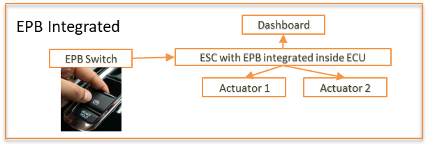
An electronic parking brake or electronic hand brake replaces a manually operated hand brake. In this project, the customer required an ASIL D compliant electronic parking brake ECU. A dedicated ECU is responsible for controlling the electronic parking brake. The ECU can be implemented in two different ways. Depending on how the OEM plans to deploy an EPB in the vehicle, we have designed two variants.

Stand Alone: As a stand-alone component, the electronic parking brake ECU activates the parking brake directly using the two actuators.

EPB system


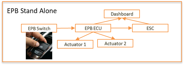
Integrated:  In the integrated format, the electronic parking brake ECU is integrated to the electronic stability control system. It activates the parking brake through commands from Electronic Stability Control system.

EPB Integrate

Case Study 2: Seating Comfort and Control System

Seating system in cars have witnessed some striking changes. Whether it is multi-way electronically adjustable seats or customized massage components, vehicle seats have come a long way. Traditionally,  the seats could be moved to either front or back using levers. While working for one of our customers, a Tier-1 supplier of automotive components, we were tasked with the responsibility to develop the entire electronic seat control and comfort system that would replace manual seat control. Let’s catch a quick overview of the system.

  • A closed loop motor control system powered with HALL sensor controls a motor (actuator) to move the seats front/back and adjust their height.
  • Seat recliners are also adjusted electronically by pressing a button or by using an HMI.

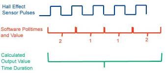
The most interesting part of this project is managing any obstacle while seat adjustment is in motion. A special algorithm has been developed to manage such scenarios. Called the Pinch out detection, the algorithm senses any kind of hindrance to the movement and aborts the seat movement. Seat adjustment will be resumed only after the users give fresh commands. Pinch out detection is achieved by HALL output that measures the load on the motor. An obstacle would mean an increased load, which would trigger a PWM signal to abort the operation.

Hall effects

In addition to electronic seat adjustment, various seat comfort systems like massage and lumbar adjustment using pneumatic controls were also part of this project.

Case Study 3: Steering Column Adjustment Control System

Steering column adjustment is a feature that lets the driver adjust the position of the steering wheel. Essentially, there are two movements found in most steering columns- tilt and telescopic. By using tilt adjustment, the height of the steering wheel can be set to the driver’s liking. Telescopic adjustment lets the steering column move back and forth. There is usually a mechanical lever that needs to be unlocked to adjust the steering.

The development of electronic steering column adjustment control system aimed to replace the lever with an electronic system. An electronic control unit is equipped with algorithms to control BLDC or AC induction motors that bring about the required movement of the steering column. Usually, two motors, one to adjust height and the other to adjust the inclination are used.

As a part of this project, the automotive team had to design, develop, and test the motor control application that would be used to adjust the steering column. Apart from the software, Embitel’s hardware team worked on the hardware and architecture design.

Conclusion

By-wire technology has been on a path of innovation. Its implementation has also been diverse. As the automotive industry gets more and more software-driven, we are likely to see several manual systems go electronic.

Embitel’s automotive engineering teams have expertise in transforming manual automotive systems to electronic or by-wire. Our expertise arises from countless such projects combined with a culture of functional safety and cybersecurity implementation. Connect with us to discover how by-wire technology can help you transform your automotive product line.


  • 0

Development of a PC based CAN data base (DBC) file to .hex file Conversion Tool


About the Customer

Our customer is an automotive tier-1 supplier and an aftermarket company pioneering in the the development of cutting-edge automotive components. The company has been working on various pathbreaking automotive innovations related to all things automotive viz. automotive lighting, telematics, and more.

Business Challenge

Automotive ECUs need to be calibrated to basis their functionality. When the communication is CAN based, CAN data base (DBC) file is converted to hex file which is then downloaded as calibration for the ECU. For one of their telematics projects, our customer required a PC based tool that would achieve this conversion from CAN DBC file to .hex file dynamically.

The major challenge that the customer was facing was linked to this dynamic conversion of dbc to .hex file. Usually, DBC files are converted to .c and .h configuration files which are added to the application code. Hence, for every variant of the ECU, the configuration file has to be generated from scratch and added to the code. Through this project, the customer aimed to make this process dynamic by a PC based tool for dbc to .hex file generation that would configure the calibration memory of the bootloader.

Embitel’s Solution

Our automotive team has delivered several projects related to the development of PC based tools. However, the conversion of CAN dbc files to .hex files was an interesting outing for them. The team chose QT as the platform to develop this PC based DBC to .hex file conversion tool.

As per the requirement of the project, there were two CAN channels and two DBCs to be configured. The tool, however, is designed in a way that it is independent of the internal network architecture and number of DBC files. It can cater to any number of calibrations, DBCs and network channels. All you need to do is to choose the desired DBC file and specify the memory location of the calibration where the .hex file needs to be uploaded.

DBC to hex converter tool
A snapshot of the CAN DBC to .hex file tool

The tool is designed to carry out this task by:

  • Downloading the DBC file provided by the OEM and displaying all network nodes of the DBC file
  • The Tx and Rx messages contained inside the DBC are
  • DBC to hex file conversion is carried out by first feeding in the Hex file start address.
  • hex file is generated and uploaded to the calibration memory of the flash bootloader.

We also provided the CAN flashing tool using which the .hex configuration file could be uploaded to the desired calibration memory.
 

Embitel’s Impact

For the fact that this tool is scalable and independent of network architecture of the ECU, it can be used to manage any number of vehicle variant with multiple calibrations. This was a big plus for the customer as this tool was future ready.

By automating the generation of hex file, the customer will be able to save a considerable amount of time and get a reliable hex file that can be readily integrated to the flash bootloader calibration memory.

Our execution of this project resulted in saving substantial resources both in terms of monetary and human resources.
 

Tools and Technologies

QT tool was used to develop this PC based .dbc to hex file conversion tool.


  • 0

How Machine Learning and AI in Sports is Redefining the Boundaries of Athlete Training

Category : Embedded Blog

In the last two decades, technological advancements have made their mark in the sports industry. With these advancements, coaches and teams have adopted improved training techniques to enhance player performances and reduce injuries.

One such improvement is the way in which Artificial Intelligence (AI) is being used in the sports industry. Today, professional sports organizations are viewing AI and Data Science as pivotal in gaining an upper hand over competition. In this article, we explore the tangible benefits of using machine learning in sports analytics.

AI in Sports – Where Does Machine Learning Come into the Picture?

IoT sports
 

One of the significant uses of Machine Learning (ML) in sports is in athlete training. With the integration of AI, performance analysis of athletes has become extremely sophisticated. When Data Science and analytics is integrated with sports, coaches can gain significant information about their players’ strengths and weaknesses. Data collected on the field can also provide interesting insights that help coaches to modify game strategy or unearth new tactics.

Let us explore this further with an example of how machine learning can revolutionize basketball training. Nowadays, basketball players training at top-level clubs use wearable technology (fitted with a sensor device) that records the player’s movements. The low-weight sensor is usually inserted into a flap on the player’s undershirt.

IMU (accelerometer, gyroscope and magnetometer) sensor collects the leaping height, running speed, and force/precision of the player’s movements, along with various other information. The data collected by these IoT powered sensors are then analyzed and fed into machine learning algorithms to determine some metrics.

Data Analytics Using Wearable Technology in a Basketball Game – Let’s Understand this Better

Phase 1 – Data collection using IMU sensor

Let’s consider that a basketball game has commenced, and the movement of players are tracked using wearable devices. For a specific player, the accelerometer will record the extent of their movement in the x, y and z axis and gyroscope will record angular movement. Such data is collected for multiple players across multiple games.

Phase 2 – Data cleaning, filtering and feature extraction

IMU sensor collects raw data. This raw data is not enough for ML algorithms to identify player activities. So, the Data Science Engineer identifies and computes relevant parameters (features) from raw data through data mining and preprocessing. The cleaned data is used for subsequent processes. These features help the algorithm to understand differences between player activities.

Data modeling is also performed to get a visual representation of the data and the interdependencies between data points.

Phase 3 – Evaluation and identification of the machine learning algorithm

Based on the problem statement and parameters, a suitable machine learning algorithm (neural networks, classification models, decision trees, regression models, etc.) is identified.

Phase 4 – Training the machine learning model

First the filtered data is segregated into ‘training data’ and ‘validation data’.

From the training data, the Data Science engineer identifies whether the player was dribbling, running, shooting or turning around and labels it accordingly. This labeled data is then fed to the machine learning algorithm for training.

In the training phase, the engineer tells the algorithm what type of action is being done for specific details of sensor data. The algorithm analyses all the players’ data and learns what kind of graph a dribble, jump, run, shoot, etc. entails.

For instance, the algorithm learns that dribbling parameters will vary between specific boundaries. And likewise, for run, shoot and jump. The next time we feed it with sensor data, it will be able to predict that the first 5 seconds of movement of a player was a run, the next 1 second is a jump, the following 2 seconds is dribbling , and so on. In case of errors in prediction, the engineer feeds the actual data to the model so that it learns better.

Phase 5 – Machine learning model prediction and analytics

After training the algorithm and validating its predictions, the engineer proceeds with the testing. The test data was never given to the algorithm while training, and it is completely fresh data. The engineer evaluates if the predictions with the test data are accurate. In case of errors at this stage, data cleaning and fine tuning of the algorithm is done again, to improve accuracy.

At the end of the testing cycle, the algorithm will be able to identify the type of action performed by the basketball player from the sensor data with a great level of accuracy. It is also possible to calculate the speed of the player while they walk, run and sprint. The engineer can then analyze these parameters for each player across multiple games to identify the progressive improvements in their game.

ML in sports

So, in a nutshell, the main approach here is supervised learning which involves feeding the ML algorithm/model with “answers” and corresponding “data” to a specific problem. The algorithm narrows down the rules and later uses these rules to make predictions. The predictions are then evaluated for accuracy over “unseen” data.

In the case of the aforementioned basketball game, the core part is in identifying activities and the duration of every activity in each game. Using these findings, a wide range of parameters are calculated and projected.

AI in Sports is Not Limited to Athlete Training

The advent of machine learning and AI in sports has opened up a plethora of opportunities and sports organizations are utilizing data to improve operations significantly. Let’s look at some of these AI use cases in sports:

  • Player development – Through Data Science, sports organizations can measure the improvements in the performance and value of each player. Organizations can also provide quick feedback to players, so that they can chart out a phased performance improvement strategy.
  • Player projection – AI in sports enables organizations to have an understanding of the future performance and risks borne by each player. This helps them to make more judicious decisions when signing contracts with players. Coaches are always focused on the condition of players when scheduling training sessions. With Data Science, they can calculate the probability of athlete injuries with higher accuracy. Player projection is essentially the foundation on which successful teams are built.
  • Game strategy optimization – When teams are equipped with the data on the strengths and weaknesses of their teammates and opponents, they can optimize their performance and game strategy to ensure a win! For instance, if teams that win consistently employ a certain strategy or perform a specific activity better than others, targeted technical training can be given to players to improve those skills. Data mining can be used on data collected from competitors to understand their key to success.
  • Improved decision making – Overhead cameras are not uncommon on football fields these days. Such cameras ensure that goals are not incorrectly given/denied. We often see on-field tracking systems in tennis courts as well, to detect line calls and assist in judging more accurately. Computer Vision is a technology that is being deployed across various sports to reduce mistakes and avoid poor refereeing decisions. Overall, sports is now increasingly embracing AI to improve the on-field decision-making process.
  • Ticket pricing – The application of AI in sports is not limited to the player development, projection, game strategy and decision-making use cases described above. Off-the-field business of sports can gain immensely by moving towards a data driven culture. Organizations can collect data on ticket pricing, price variations and sales across various sites. They can then optimize the pricing strategy and even change the pricing as the matches get closer, to maximize revenue.

That’s not all, there are several other opportunities for AI application in sports. Here’s a snapshot of some of those areas:

ML in the sports


Although most sports organizations collect a large amount of data from players on the field, they have traditionally faced challenges in making sense of this data. The most optimum approach to close this gap is to partner with experienced machine learning engineers.

Key Takeaways

The power of machine learning and AI in sports has helped us unlock avenues that never existed before. Without doubt, AI will continue to transform sports in the way it is played, watched and analyzed.

Artificial Intelligence will provide players and coaches with a huge advantage over those who rely solely on human experience and intuition. It is, hence, important for coaches at the highest level to have at least a small amount of working knowledge on Data Science. Likewise, Data Science specialists should also be aware of the intricacies of the sport, at a high level.

AI in sports holds a huge promise for the future and it will be very exciting to track its growth! Watch this space for more interesting articles on AI and ML technology.


  • 0

Development and Testing of Electronic Steering Column Adjustment System for an Automotive Tier-1

About the Customer

We partnered with an automotive Tier-1 supplier with a vision to develop future-ready automotive solutions. Our collaboration with this company spans multiple projects related to solution development, ISO 26262 compliance, verification and validation support, flash bootloader development and more.

Business Challenge

Our customer was developing an electronic steering adjustment system (Tilt and telescopic). Since the project follows ASPICE standard, development and complete testing of the system also needs to be performed as per ASPICE. Unit Testing, Integration Testing, and Functional testing (System testing) of such a complex solution requires enormous amount of man hours, if performed manually.

Key challenges:

  • Expertise required for tools like VT system for HIL testing
  • ASPICE system level 2 expertise was required
  • Expertise in tools for Unit testing, integration testing and static code analysis

To mitigate these challenges and complete the testing as per ASPICE standard, the customer came on-board with us.

Embitel’s Solution

Phase-wise release of the solution was planned during the discussions with the customer and our development team.

Following aspects were part of the project plan:

  • Software design, implementation, and testing
  • Hardware design, implementation, and testing
  • System design and testing (HIL testing using VT system)
  • ASPICE compliance by maintaining bi-direction traceability, so that every point in the report traces back to a requirement

Entire spectrum of testing right from unit testing and integration testing to software qualification testing was covered during the project lifecycle. The testing team was built in a way to include experts of all forms of testing.

Final Deliverables of the Testing Activities:

  • Summary test report
  • Release report
  • Separate document listing issues raised during testing
  • Diagnostics and fault testing document (open current, overload current)

We followed the ASPICE v3.1 standard document for planning and executing the test activities.

ASPICE v3.1 standard
 

Embitel’s Impact

We automated the functional testing of ECU which resulted in 70-80% of code being tested in the automation mode. Using CAPL scripting, the test cases were automated and the execution of tests took only 4-5 hours. It would have otherwise taken 1-2 weeks for manual testing.
 

Tools and Technologies

DOORS tool: DOORS is a requirement management tool. It is used to create test cases based on the requirements.

V Test Studio: V Test Studio is a test authoring tool for embedded systems.

CANoe: It is a software tool for development, test and analysis of automotive ECUs.

CAPL: CAPL scripting is used to automate test case creation and execution.


  • 0

How does Functional Safety Apply to Digital Instrument Cluster?

Category : Embedded Blog

Car manufacturers have been able to enhance driving experiences by adding various interfaces to vehicle dashboards. So, when your screen flashes low tire pressure, it is in a way adding years to the tire’s life, maintaining fuel efficiency, and ensuring better ride quality. Timely and accurate display of tell tales like tire-pressure, seatbelt sign, door open/close warnings go a long way in ensuring that the driver and occupants are safe and are able to enjoy an enhanced ride quality.

The keywords to be noted in the previous paragraph are ‘timely’ and ‘accurate’. And it is due to these two very important factors that functional safety comes into the game. Automotive displays like Digital Instrument Cluster provide safety-critical information to the driver through visual alerts like flashing lights. If you add ADAS related warnings to the mix, you get an instrument cluster that is safety-critical to its highest limit, i.e., ASIL D. It is essential that such a cluster is highly reliable and displays warnings about safety-critical functionality with utmost accuracy. And in order to achieve such reliability, adherence to ISO 26262 standard is the way to go.

ISO 26262 for digital instrument clusters does not work differently. You have the same lifecycle to follow, beginning with item definition, HARA, various safety analyses like FMEA, FTA and testing. So why are we writing a whole new article stressing about FuSa for digital instrument cluster?

For one, as a technology provider, we have been fortunate to work on some really challenging ISO 26262 compliant digital instrument cluster projects. Another reason is that instrument clusters and other automotive displays are not usually considered safety critical. ASIL is assigned to them based on assumptions or industry norms. And that can prove to be a disaster in more ways than one can imagine.

A Closer Look into Digital Instrument Cluster to Understand Its Safety-Criticality

The first ever application of an instrument cluster in a passenger vehicle was in an Aston Martin vehicle in the year 1979. It was a basic instrument cluster showing vehicle speed, kilometers driven and fuel meter, to name a few. Fast forward to the era of e-cockpit*, digital instrument cluster is a goldmine of vehicle information.


*E-cockpit is a concept where an interactive multi-dimensional control center displays a wealth of vehicle related information on the screen and lets the vehicle occupant control a host of vehicle features with a few clicks. Usually, an e-cockpit comprises infotainment system, digital instrument cluster and head-up display.


A digital instrument cluster completely replaces a traditional analog instrument cluster. To make it truly digital, a combination of system-on-chip (SOC), display unit and software work in tandem. OEMs design instrument clusters in a very personalized manner; however, there are certain functionalities that most advanced clusters will have:

  • Vehicle information (speed, tell tales, battery, etc.)
  • Turn-by turn navigation system
  • Call alert
  • Weather information
  • Music playback display
  • Mechanism to upgrade the software/firmware
  • On-board ambient light sensor

An instrument cluster system collects vehicle information from various ECUs and sensors through the vehicle network systems such as CAN, LIN, FlexRay and even Ethernet. There are interfaces such as communication interface and audio interface that make the data available to the instrument cluster display. The diagram below highlights all the elements that constitute a digital instrument cluster.

Whether a connected cluster is safety-critical is roughly decided by the kind of signals it is transmitting, processing and displaying. Obviously, a detailed HARA should be done to ascertain the ASIL value and safety goals.

The following elements of the digital instrument cluster are considered in the safety scope:

1 Control logic This executes all core algorithms and functionalities. It controls all major components and achieves the safety measures required in the system.
2 Internal power management Provides regulated safe power supply to various elements. Certain safety features need to be implemented in this element.
3 Communication interface Includes Protocol specific transceivers, connectors, harness, etc.
4 Self-Diagnosis On board fault detection and handling mechanisms.
5 Temperature sensor To monitor the processor board surrounding temperature.
6 Ambient light sensor To adjust the display brightness automatically.
7 Display An interface/driver to make sure the display is set properly and helps to show the content in the display. However, this is not responsible for all display faults occurring during the runtime.
8 Display Driver If any fault is sent by display, it resets the fault by taking the appropriate action, such as restarting the display or switching it off.
9 Buzzer/Speaker To play the Audio for important alerts, warnings, and errors.
10 Audio driver/interface Helps to decode and play the audio and send to speaker.

All these elements are responsible for making the digital instrument cluster perform its function. It also implies that these elements need to be developed in accordance with ISO 26262 standards, depending on the highest ASIL they are assigned during HARA.

Now let’s pick one of the elements and see how a fault can compromise safety. Let’s consider the use case where the speedometer gives the wrong speed and the driver drives well above the speed limit, risking himself and the rest of the traffic. Another critical scenario may occur when a failure indicator is not turned on, e.g., brake failure, airbag failure, or an engine failure. Another example could be of the unintentional blinking of a warning light that could force the driver to take actions that would not be warranted at that instance.

The failure modes of these elements are identified during FMEA (Failure Mode and Effects Analysis). Most common failure modes are:

  • Loss of function
  • Degraded function
  • Displaying incorrect information
  • Failure to indicate by audio method- speaker failure
  • Delay in displaying data

How ISO 26262 Compliance Works with the Digital Instrument Cluster

The safety lifecycle for any automotive solution begins with the determination of ASIL and safety goals. And digital instrument cluster is no exception. In order to perform HARA and determine ASIL, we first need an item definition. The table of elements that we showed in the previous section can be seen as a simplified item definition. Every parameter associated with each of the element needs to be analyzed when performing HARA.

For instance, in one of our connected cluster projects, we were developing an instrument cluster that would take in data from vehicle ECUs via CAN and on top of that, it would also display navigation by communicating with the infotainment system over Ethernet. So, all these parameters would be considered while performing HARA.

A few additional information identified during the preparation of item definition also help in HARA. Knowledge of dependence of the elements on external items and dependence of external items on the instrument cluster can be very helpful. Sample these:

  • The cluster must be able to display vehicle-critical info received by CAN gateway.
  • It should be able to update the system by receiving the firmware update from relevant ECU.
  • The cluster should be able to write data to CAN gateway; for instance, resetting the trip meter to zero.

Some general assumptions are also made during item definition such as:

  • The cluster should be able to start only after performing safety checks.
  • Scenarios like under- or over-voltage must be monitored always and there should be a provision for the cluster to switch off in case of any major fault.

Now, let’s take a look at the some of the safety goals and ASIL values for the components analyzed during HARA.

Let’s consider the safety goals and ASIL for the function– telltale sign for ABS.

Function Safety Goals ASIL of SG Safe State
Telltale for ABS Unintended activation of ABS malfunction telltale should be avoided ASIL A Fail Stop
Loss of ABS malfunction telltale should be avoided ASIL B Fail Indicate
Unintended activation of low brake pressure telltale should be avoided ASIL B Fail Operational

When the safety goals and ASIL are determined, the rest of the safety lifecycle is dedicated towards implementing the safety mechanism required to achieve the safety goals. With every artefact such as Technical safety requirements, functional safety requirements, the requirements get more and more refined.

Safety analyses such as FMEA, FMEDA, FTA, etc. help in deriving failure modes, certain hardware metrics, faults, and their origin and a whole lot of relevant work products. For example, the decision to have a companion MCU to handle safety-critical signal (shown in the image below) comes from these analyses.

Digital instrument cluster, along with infotainment system, has been one of our key areas of expertise. We are also one of the early adopters of automotive functional safety as a culture in our automotive team and are proud to have delivered a large number of ISO 26262 compliant solutions to our global customers.

Get in touch with us at sales@embitel.com to learn more about our experience in this domain.