×

Happy to Help!

This website doesn't store cookies. Enjoy the experience, without worrying about your data!

Great, thanks!

Category Archives: Vehicle Diagnostics

  • 0

Software and Hardware Development for DC-DC Converter ECU

About the Customer

Our customer is an automotive after-market organization delivering excellence through a wide range of automotive components. Within a few years of its inception, our customer has been able to carve a niche for itself due to its commitment to quality and disruptive innovation.
 

Business Challenge

Harnessing green energy in an efficient manner can bridge the looming energy gap, especially in the automotive industry. Our customer’s ambitious project had ‘solar energy harnessing’ at its core. In technical terms, the project aims at developing a DC-DC converter for passenger vehicles. The role of the DC-DC converter is to take in the energy from a solar panel and convert it to a voltage component that can be supplied to charge a vehicle’s battery.

The challenge that our customer was facing in realizing this project were manifold:

  • Our customer’s team was not well-versed with MATLAB and other MBD tools required to develop such an application.
  • Lack of expertise in LIN based bootloader and platform software

We got on-board the project due to our extensive experience in both software and hardware design and development using a model-based approach. On top of it, our ready-to-integrate LIN stack and pre-built platform software modules gave us an edge.
 

Embitel’s Solution

We were entrusted with end-to-end development of the DC-DC converter, i.e., software, hardware, and platform software (BSW) development.

The software and hardware teams at Embitel worked on the project simultaneously as we were on a strict deadline to finish the project.

Major highlights of the DC-DC converter ECU:

  • The ECU takes voltage and current (V,I) input from the PV (photo voltaic) cells of the solar panel and generates the required voltage (12/48 volts) for the battery to charge.
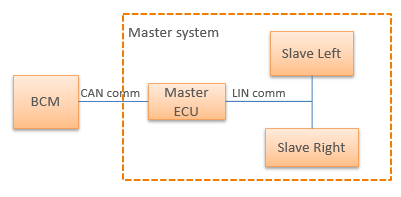
  • The ECU connects to the energy management ECU via LIN protocol to measure the voltage required by the battery for charging.
  • It is a closed loop control mechanism with a feedback loop that measures the output and instructs the DC-DC converter ECU to optimize the output voltage if it deviates from the expected value.

Here’s a snapshot of our complete DC-DC converter solution for vehicle ECU:
 

Software Application:

  • The software part comprises of a DC-DC converter ECU with closed loop control algorithm to generate the required voltage.
  • It is a configurable solution which can be modified for different vehicle and battery variants.
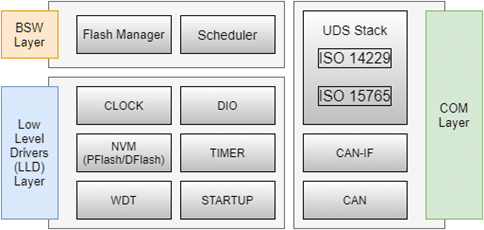
  • We have developed the complete platform software (BSW) for the solution.


Hardware Design:

  • Our hardware team has performed hardware design and simulation.
  • Board bring-up and pre-compliance test have been performed successfully.


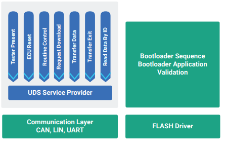
Vehicle Diagnostics and Bootloader

  • We have provided vehicle diagnostics powered by UDS over LIN.
  • Flash bootloader over LIN is a part of the solution to enable ECU reprogramming.

Embitel’s Impact

We had a strict timeframe to complete the first leg of the project. Our ready-to-integrate LIN stack, pre-built platform software and expertise in MATLAB Simulink were instrumental in helping us stick to the deadline.
 

Tools and Technologies

  • Ti TMS320- Microcontroller platform
  • Code Composer- IDE and Compiler
  • CANoE – Communication
  • Matlab – Application Development
  • OrCAD- Hardware Circuit Design
  • Altium- Hardware simulation

  • 0

Development of a PC based CAN data base (DBC) file to .hex file Conversion Tool


About the Customer

Our customer is an automotive tier-1 supplier and an aftermarket company pioneering in the the development of cutting-edge automotive components. The company has been working on various pathbreaking automotive innovations related to all things automotive viz. automotive lighting, telematics, and more.

Business Challenge

Automotive ECUs need to be calibrated to basis their functionality. When the communication is CAN based, CAN data base (DBC) file is converted to hex file which is then downloaded as calibration for the ECU. For one of their telematics projects, our customer required a PC based tool that would achieve this conversion from CAN DBC file to .hex file dynamically.

The major challenge that the customer was facing was linked to this dynamic conversion of dbc to .hex file. Usually, DBC files are converted to .c and .h configuration files which are added to the application code. Hence, for every variant of the ECU, the configuration file has to be generated from scratch and added to the code. Through this project, the customer aimed to make this process dynamic by a PC based tool for dbc to .hex file generation that would configure the calibration memory of the bootloader.

Embitel’s Solution

Our automotive team has delivered several projects related to the development of PC based tools. However, the conversion of CAN dbc files to .hex files was an interesting outing for them. The team chose QT as the platform to develop this PC based DBC to .hex file conversion tool.

As per the requirement of the project, there were two CAN channels and two DBCs to be configured. The tool, however, is designed in a way that it is independent of the internal network architecture and number of DBC files. It can cater to any number of calibrations, DBCs and network channels. All you need to do is to choose the desired DBC file and specify the memory location of the calibration where the .hex file needs to be uploaded.

DBC to hex converter tool
A snapshot of the CAN DBC to .hex file tool

The tool is designed to carry out this task by:

  • Downloading the DBC file provided by the OEM and displaying all network nodes of the DBC file
  • The Tx and Rx messages contained inside the DBC are
  • DBC to hex file conversion is carried out by first feeding in the Hex file start address.
  • hex file is generated and uploaded to the calibration memory of the flash bootloader.

We also provided the CAN flashing tool using which the .hex configuration file could be uploaded to the desired calibration memory.
 

Embitel’s Impact

For the fact that this tool is scalable and independent of network architecture of the ECU, it can be used to manage any number of vehicle variant with multiple calibrations. This was a big plus for the customer as this tool was future ready.

By automating the generation of hex file, the customer will be able to save a considerable amount of time and get a reliable hex file that can be readily integrated to the flash bootloader calibration memory.

Our execution of this project resulted in saving substantial resources both in terms of monetary and human resources.
 

Tools and Technologies

QT tool was used to develop this PC based .dbc to hex file conversion tool.


  • 0

Partnership with a Tier-1 for Migration of an ECU Application Software to MBD Approach

 
Our customer is a tier-1 supplier of automotive ECUs for hybrid and combustion engine vehicles.

Business Challenge

Our customer has a working automotive ECU control software for one of the vehicle applications developed using conventional coding. There is a growing demand in the market for systems & devices which are compact, customizable, durable and easily maintainable. Owing to this factor, the customer wanted to migrate to the model based design paradigm.

Essentially, the customer was looking for a technology partner with experience in:

  • Engineering approach that supports all stages of development with ease of verification & validation. This results in a system that works seamlessly across different environments.
  • The approach should be in sync with the existing system with conventional C code.

Embitel’s Solution

Since our team was tasked with migrating an existing system to the MBD paradigm, we first performed a joint analysis and study of the existing systems with the customer’s team. We analysed the different components of the application software and identified the following approach for migration to MBD:

  • Model Based Development approach for the development of the application software.
  • Development and use of the custom-built Simulink library blocks to match the existing software functions.
  • Use of script where the existing application software (.c/.h) files are processed to generate Model and Data Dictionary templates.
  • Fixed point modelling.
  • Matching the Model Based Development software functionality with the earlier software functionality by Auto code generation using Embedded coder tool.

Development steps in the migration process:

  • Scripts are run on the .c/.h files of the existing application modules post which Data Dictionary and model template are generated. The model template consists of the Simulink function subsystems blocks.
  • The C code is analyzed, and model is grown by implementing the C function logic inside the Simulink function subsystem block.
  • The data dictionary is updated with the data properties similar to the existing system and model is prepared for code generation.
  • Model is verified by compiling and upon successful verification code is generated.
  • The auto-generated code is compared with the existing C code and reviewed by the customer.
  • Post verification, the code is integrated with the existing system where the auto code generated files replaces the .c/.h files of the existing system.
  • The MBD integrated software is tested to match the functionality of the existing system.


Embitel’s Impact

  • The MBD approach helped to develop the application software system that is easily configurable and
    maintainable to support future changes.
  • The use of scripts reduced the development time significantly and also the manual errors intervention during the data dictionary creation.
  • We used the Standard library blocks for the PID controllers, inputs filters, n-D lookup tables etc., thereby reducing the development time significantly.
  • Model simulation testing helped to identify the issues early.


Tools and Technology

  • Matlab
  • Simulink
  • Stateflow
  • Embedded coder
  • NXP’s S32 Design Studio for Power Architecture

  • 0

Development of Volkswagen Specific Bootloader Development for an Automotive Tier-1 Customer


About the customer

Our customer is a prominent tier-2 supplier of electronics and mechanical systems for various industries, automotive being the most crucial one.

Business Challenge

Every ECU needs a flash bootloader for ECU flashing and re-programming. For one of their recent projects our customer wanted such a bootloader solution, but with some specific requirements. One of the major requirements entailed the bootloader to be specific to Volkswagen OEM guidelines. Every OEM configures their bootloader with re-programming strategies and data integrity mechanisms specific to them.

These parameters may be related to how data is communicated, kind of seed-key algorithms in place and various other aspects. Developing a VW specific bootloader over UDS from ground-zero would mean at least 6 months of development time which would reduce the time-to-market further. A ready-to-deploy UDS software was the first requisite for this bootloader to work.

Upon learning about our flash bootloader development capabilities and the prior customers that we delivered our bootloader to, the customer came on-board.

Embitel Solution

Our task was to provide a complete solution to enable ECU re-programming. Since the ECU was intended for VW, the flash bootloader software had to be developed as per the OEM specifications. The bootloader development also brought about the need for a UDS protocol software and a PC based ECU-reprogramming tool along with the low-level drivers for the Microcontroller unit on which the Bootloader will run.

Microcontroller unit

Our final deliverables to the customer were:

UDS Stack- Service level configuration and DID level configurations were performed to our ready-to-integrate UDS protocol stack.

Bootloader Development: Bootloader software was developed as per the OEM specifications which in this case was Volkswagen. Since we had worked on a somewhat similar Bootloader project before, we had the basic bootloader framework and architecture ready.

PC based Re-programming tool: It was developed for re-programming the ECU as per Volkswagen specifications including data transmission mechanisms and seed-key algorithm. The tool was developed in QT based C++ environment.

Low-level drivers: Thanks to our vast library of platform software solutions, we could re-use our low-level drivers for this project.
 

Embitel Impact

50-60% of effort was saved since we had platform software ready for the microcontroller platform that our customer intended to use for their project. The ready-to-deploy UDS stack and Bootloader framework also contributed to faster time-to-market for the solution.
 

Tools and Technologies

IAR Embedded workbench: Compiler used for development

QT, C++: A cross-platform application and UI framework used to write applications for multiple platforms.

Vector Hardware Interface: Acts as an interface between the PC based software and embedded hardware

CAPL Script: A scripting language used to access CAN protocol for simulation purposes


  • 0

Execution of Preliminary HARA for a Commercial Vehicle Infotainment System


About the Customer

Our customer is a US-based manufacturer of electric commercial vehicles that cater to various transportation needs. Reducing the cost of vehicle development through innovation is at the core of their organization.

Business Challenge

Working on the digital instrument cluster and telematics gateway solution for the customer, we realized that these components are safety-critical and must come under the purview of ISO 26262 compliant functional safety.

Our FuSa team got in touch with the customer and shared these views to which they agreed. However, to be clear about the approach to ISO 26262 compliance, it was important to have an ASIL value assigned to the solution.

Embitel Solution

A dedicated team of Functional Safety experts analyzed the project and concluded that a pre-liminary HARA (Hazard Analysis and Risk Assessment) would be the ideal approach to find a reference ASIL value.

Advantage of pre-HARA is that it does not require a full-blown effort from the FuSa team and is also economical to the customer. We have covered important hazards in the pre-HARA process so as to have an idea of ASIL for the solution Embitel is developing.

Since, the customer did not have ‘Item Definition’ ready with them, our proactive FuSa experts made use of the hardware specification as the input to pre-HARA.

A Snapshot of Pre-HARA for Digital Instrument Cluster and Telematics:

  • Functions to be analysed were categorized based on the different components of the system.
  • Operating modes, scenarios and environment factors were identified as per the ISO 26262 guidelines.
  • Based on these factors, each function was analysed for associated hazards and classification was done according to severity, exposure and controllability.
  • ASIL was determined using the allocation table.
  • In addition, few safety goals were also identified.

Since, we were performing HARA for a digital instrument cluster, the focus was on the digital gauge and tell-tales. An example of both will make things clearer.

Digital Instrument Cluster HARA ISO 26262


Tell-Tales

Tell Tales HARA ISO 26262


We identified similar hazards for different functions and based on complete analysis, we came up with ASIL-B to be assigned for the solution. In addition, we were also able to identify certain safety goals which would be strengthened upon complete HARA.
 

Embitel Impact

With pre-HARA, the customer was clear about the ASIL to be targeted. Having this understanding in the early stages helps in planning the path ahead. This process helped our customer in developing a safe solution, one that is ISO 26262 compliant.
 

Tools and Technologies

MS Excel: The pre-HARA template is created on MS excel and filled by FuSa experts.


  • 0

UDS based Flash Bootloader Development, Configuration, and Integration Using V-Flash Tool

About the Customer

Our customer is a reputed tier-1 supplier of automotive components and has been developing a series of innovative solutions for the industry. Our partnership with the customer has been a longstanding one with several collaborations. The customer has been a witness to our expertise in automotive software development and suite of ready solutions. It was one of the reasons we were brought on-board this project.

Business Challenge

The fundamental requirement of the project was to develop and configure UDS based bootloader for ECU flashing over CAN. A UDS based bootloader was needed to transfer vehicle diagnostic related data to the ECUs. In order to achieve the desired output from the bootloader, the customer wanted the flash bootloader to be 2-level- Primary Bootloader and Secondary Bootloader.
Implementation of diagnostic services as per UDS protocol was one of the challenges faced by the customer. A team with relevant skill set and experience was also required to develop a flash bootloader equipped with the codes to achieve diagnostic communication.

Critical phases/requirements were identified during the multiple discussions our automotive team had with the customer’s team:

  • Development of low-level drivers required for the Bootloader operation
  • Base software development including flash manager and scheduler
  • ECU communication stack- CAN and vehicle diagnostics stack implementation (UDS)
  • Bootloader Development and configuration using V-Flash from Vector
  • Implementation of algorithms including seed and key generation and data validation

Embitel Solution

After finalizing the project scope and the deliverables, our automotive team swung into action. The software architecture of the UDS based bootloader was sketched out with clearly defined components. As we had a few re-usable components such as UDS software and CAN protocol software, we focused our efforts on the development of the flash bootloader. As per the customer’s requirement, we deployed VFlash tool from Vector for ECU reprogramming and bootloader configuration.

VFlash tool

 
Following deliverables were provided along with configuration and integration support:

  1. UDS based Flash bootloader
    • Development of Primary and Secondary Bootloader
    • Configuration of Bootloader using template created by V-Flash tool
    • Development of bootloader programming application (P-Flash)
    • D-Flash reprogramming
    • Seed and Key generation algorithm development
    • Bootloader security modules- SHA 256, CRC algorithm etc.
    • Data validation support
  2. Integration of UDS protocol software to implement vehicle diagnostic services
  3. CAN protocol stack configuration as per DBC file
  4. Base software and low-level device driver development including scheduler, watchdog and flash manager


Embitel Impact

Our timely delivered solution reduced the time-to-market of the product by more than 6-8 weeks. We deployed some of our re-usable stacks such as CAN-IF, CAN NM and UDS protocol software to further reduce the development time. Configuration time was also considerably reduced due to our proprietary CAN and UDS configuration tool.
 

Tools and Technologies

Vflash software from Vector: Bootloader configuration, parameterization

Vector Canoe- ECU Flashing tool

IDE and debugger: ATMEL and MP Lab X IDE from Microchip


  • 0

Safety Analysis (FMEA, FMEDA) for ASIL C Compliant Automotive Lighting Solution


About the Customer

Our customer is an automotive Tier-1 supplier of vehicle ECU, lighting and various other automotive parts.

We have had a successful partnership on a futuristic project on automotive lighting. The mutual trust and respect were taken a few notches higher with this ISO 26262 project.

As our customer had previously worked with us, they were aware of our ISO 26262 capabilities and hence, we were the choice partners for this project.
 

Business Challenge

While working on an automotive lighting system, our customer realized the need for its ASIL C compliance. The lighting module’s proposed application in the vehicle system made it a safety-critical component.

Our customer, a pioneer in automotive components development did not have the ISO 26262 processes in place.

Setting up the processes, hiring ISO 26262 consultants, purchasing ISO 26262 qualified tool licenses and training the engineering team on ISO 26262 standard would escalate the project cost and increase time-to-market.

Moreover, the customer was looking for a technology partner that:

  • Could provide support for both qualitative as well as quantitative safety activities
  • Had prior experience of working on ASIL C compliant projects
  • Was able to perform both hardware and software safety analyses
  • Had expertise on ISO 26262 qualified tools like Tessy
  • Had experience of providing safety analysis activities for the entire safety lifecycle- Concept Phase to Product Development

The customer was aware of our maturity in ISO 26262 standard adoption, FuSa expertise and trained engineering team.
 

Embitel Solution

The customer required both qualitative and quantitative analysis of the software and hardware. Our FuSa team figured out that a series of safety analysis activities will need to be performed:

A snapshot of the solution provided by our team:

  • Safety management activities were planned as per ASIL C including safety plan and DIA (Development Interface Agreement).
  • We developed safety compliant hardware and software implementation for master and slave ECUs.
  • Our team performed System Failure Mode and Effects Analysis (FMEA).
  • ASIL C compliant Hardware and Software safety analyses were performed. This included:
    1. Software FMEA
    2. Hardware FMEA
    3. Dependent Failure Analysis (DFA)
    4. Fault Tree Analysis and HW FMEDA
  • Performed Static analysis using Polyspace.
  • Performed Unit testing using Tessy.
ASIL C Compliant Automotive


Embitel Impact

As deliverables of the project, we provided the work-products that were required for ASIL C compliance. These work-products included report of FMEA, FMEDA, FTA, DFA and other ISO 26262 compliant safety analysis.

As a result of these safety analyses, we were able to strengthen the existing safety mechanism of the system.

With a fully-trained and well-structured team of ISO 26262 experts, we were able to save a considerable amount of time for the customer. This led to a faster time-to-market for the lighting product.
 

Tools and Technologies

Enco SOX: Used for safety analysis like FMEA, FMEDA, etc.

Vector CANoe: Used to simulate vehicle ECU during functional testing

Polyspace: Helped in static analysis of the code as per the ISO 26262 guidelines

Tessy Tool: An ISO 26262 qualified tool, it is widely-used unit testing tool


  • 0

Integration of J1939 stack with an advanced EPS system | Automotive Tier-I Supplier


The client, a trusted and reputed Automotive Tier-I Supplier of steering and driveline components, approached our Automotive Embedded Services team to resolve a very challenging embedded software development issue.

This hurdle was a grave one-it had the potential to derail the product roadmap of their futuristic Electronic Power Steering (EPS) system.

Here is the complete success story!


Business Challenge:

Our client had successfully embarked on their journey of designing an advanced Electronic Power Steering (EPS) system for Commercial vehicles. The following critical phases of product development lifecycle were already complete:

  • Hardware design based on DsPIC 30F4011 Microchip Platform
  • All the necessary components and hardware modules were identified and finalized as per the design needs
  • In-vehicle testing of the hardware was complete
  • EMI and EMC certification-related compliance was also successfully achieved
  • PCB manufacturing phase was completed

However, the customer encountered a major roadblock during software porting.Due to limited on-chip memory (RAM and ROM) of DsPIC 30F4011 platform, it became imperative for the customer to port highly-optimized embedded software to the EPS system.

Re-designing or changing the hardware platform would have impacted the bottomline of the project negatively, leading to substantial financial loss. Also, the DsPIC Microchip platform was best suited for the required EPS application, meaning that the only feasible resolution was an Optimized Embedded Software.


Embitel Solution: the re-usable and layered architecture based J1939 stack:

After several engineering workshops with the customer for understanding and analyzing the EPS system, Team Embitel was able to overcome the hurdle with the help of following solution:

  • A light-weight and re-usable SAE J1939 compliant stack best suited for commercial vehicles was integrated with the system
  • The entire code was optimized around J1939 stack and since the stack has layered architecture, the optimized software was successfully ported thus overcoming the memory issue

SAE J1939 – Project details:

  • SAE J1939 complaint Boot Loader was also ported to facilitate Reprogramming of ECUs efficiently and securely via CAN network
  • The ported J1939 stack consisted of J1939 Data Link and Transport Layer (J1939\21), Network Management layer (J1939/81), Vehicle Application Layer (J1939/71) and Vehicle Diagnostics Layer (J1939/73)
  • All this ensured support for vehicle communication, reprogramming, diagnostics and fault code memory
  • All the necessary device drivers were designed, developed and ported by Embitel
  • The EPS being an OS-independent system (non-RTOS), a Scheduler was also ported as shown in the system architecture diagram
  • Onsite support for integration of stack with client’s application and in-vehicle testing services were also extended as part of this successful engagement
  • J1939 stack also ensured Enhanced Portability for the steering system (Support for 8, 16 and 32 bit Embedded Controllers)
J1939-Stack
Embitel Impact:
  • Timely resolution of the software issue by designing a highly optimized and high quality code
  • Integration of re-usable J1939 stack not only safe-guarded the client’s product roadmap but also ensured speed-to-market and cost savings

What is SAE J1939?

Society of Automotive Engineers (SAE) J1939 is the vehicle bus recommended practice used for communication and diagnostics among vehicle components.

SAE J1939 is used in the commercial vehicle area for communication throughout the vehicle, with the physical layer defined in ISO 11898.

Source – Wikipedia


  • 0

Android In Vehicle Infotainment System

The aim of this Android In vehicle infotainment system based on Freescale i.MX6 application processor platform, is to present a secondary vehicle dashboard with OBD Information along with all the entertainment features provided to exploit an Android ICS OS.

Freescale i.MX6 series unleashes the industry’s first truly scalable multicore platform on the ARM® Cortexᵀᴹ-A9 architecture. Together with robust ecosystem. i.MX6 series provides the ideal platform to develop a portfolio of smart automotive infotainment devices based on a single hardware design.

i.MX6 Quad Core CPU @ 1Ghz and 1GB DDR3 ram, which supports the following functionalities
  1. CAN connectivity
  2. WiFi
  3. Bluetooth
  4. GPS
  5. GSM module
  6. Micro SD & USB 2.0 Host
  7. Ethernet
  8. SATA 3.0
  9. HDMI 1080p
Main Features

The device boots-up with Android ROM customized for IVI specific functionalities. Once the device is booted, it displays a dashboard with application icons and the Touch enabled screen allows the user to effortlessly launch different IVI applications like

android in vehicle infotainment

  • Vehicle Instrumentation Cluster
  • Navigation System
  • Music Player
  • Image Gallery
  • Internet Browser
  • Video Player
  • File Manager
  • Settings

  • 0

OBD2 Software Development and Testing for an ECU Application

OBD or On-Board Diagnostics refers to a system for emission control which has the capability to detect a malfunction and to store the related information in non-volatile memory. The OBD system monitors the emission relevant components or systems, stores detected malfunctions indicating likely area of malfunction and activates Malfunction Indicator Lamp (MIL) if necessary.

The Objectives of OBD regulation are,

  • To improve in-house emission compliance by alerting the vehicle operator when a malfunction exists
  • To aid automobile repair technicians in identifying and repairing malfunctioning systems in the emission control system.

OBD diagnostic interface refers to functionally addressed request/response messages to access the OBD relevant information from the vehicle using a generic OBD scan tool.

Requirements

The scope of the project was to design, implement and test OBD-II functionality in an Engine Control Unit. The scope of the project covered the following modules.

  • Diagnostic System Manager (Diagnostic Manager and Fault Code Memory) – On board diagnostic functionality to detect and store malfunctions
  • OBD Diagnostic Interface – To provide external tester access to stored OBD data