×

Happy to Help!

This website doesn't store cookies. Enjoy the experience, without worrying about your data!

Great, thanks!

Category Archives: Automotive control units-design and development

  • 0

Development of an ISO 21434 Based Secure Bootloader for an Automotive Tier-1


About the Customer

Our customer is an automotive tier-1 specializing in innovative solutions around mechatronics of automobiles. Some of the leading OEMs around the globe trust them for their sophisticated solutions.

As the industry is fast embracing automotive cybersecurity, our customer has been one of the earliest adopters of cybersecurity standards and practices. Partnering with us takes their commitment to automotive cybersecurity to newer heights.

Business Challenge

The primary challenge for our customer was to develop a secure bootloader that could flash/reprogram the ECU (control unit). There was a certain level of cybersecurity required for the ECU that entailed numerous security implementations including digital signature.

Here’s a snapshot of the major challenges that needed to be addressed:

  • The ECU comprised 2 microcontrollers that required a 1-wire gateway
  • Both CAN and LIN based bootloader was required as ECU had both CAN and LIN variant.
  • The Hardware Security Module provided by Microchip required drivers to be developed
  • Secure Bootloader was needed to be developed with advanced cybersecurity features as per ISO 21434 standard

Since the customer needed a faster time-to-market for their solution, they partnered with us for bootloader development and other solutions. We have a proven track record of delivering secure bootloaders for automotive ECUs.

Embitel’s Solution

Our automotive team was primarily tasked with the development of a secure bootloader that would interact with the Hardware Security Module (HSM) of the ECU and ensure secure ECU flashing. In the process, the image(.hex/.srec) file and the digital signature will be validated with the HSM.

Additionally, the project scope also included developing a ‘gateway’ to facilitate flashing of 2 microcontrollers. Since the ECU had two variants- CAN and LIN, we had to develop bootloaders for both networks.

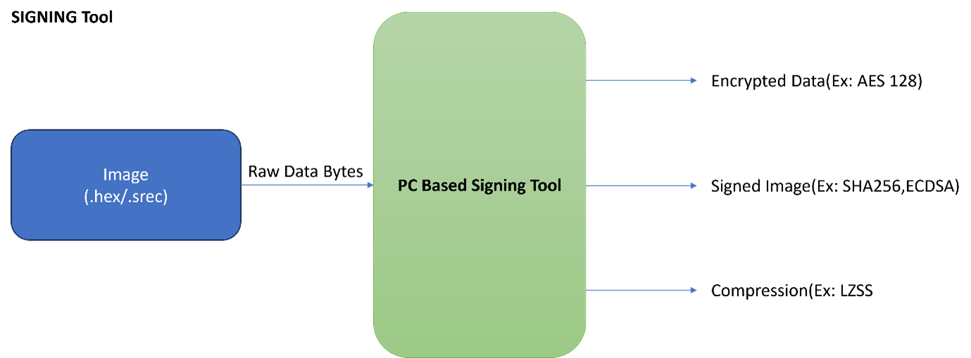
To facilitate secure ECU flashing, our customer requested us to develop a signing tool that would encrypt the image (.hex/.srec) file based on algorithms required by the customer.

The team started to work parallelly on these three applications.

Details of the solutions built for the customer:

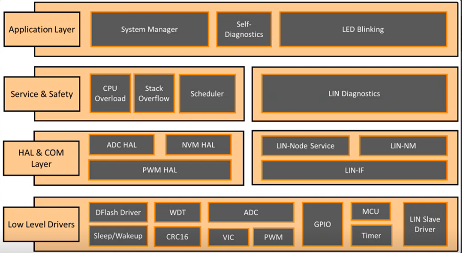
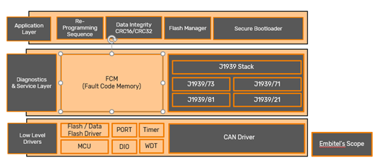
  • Secure Bootloader: The secure bootloader comprises of algorithms such as AES- 128, Elliptical Curve Digital Signature algorithm (ECDSA), CRC-32 integrity and data authenticity mechanism. We developed the secure bootloader for both CAN and LIN protocols as requested by the customer.
  • Low-level drivers required by the microcontroller: Device drivers such as HSM drivers and all other low-level drivers needed by the microcontrollers such as NVM handler, CAN, LIN drivers were developed.
  • 1-wire Gateway: The data coming for microcontroller 2 has to be forwarded from microcontroller 1. We developed a secure gateway for that purpose. It is a UART based 1-wire gateway solely for transmitting data from one MCU to another.

    Gateway proved to be a critical piece of solution to build especially in a 2 MCU environment. The gateway must ensure that the number of bytes of data sent to MCU 2 is received without any loss. Also, the data sent to MCU 2 through the gateway must be validated through HSM. Hence, reliability is the key here. We tested the communication rigorously to rule out any discrepancies.

  • Signing Tool: We developed the signing tool to solve the problem of encrypting the firmware image file based on secure algorithms of choice. The signing tool accepts .hex or .srec application images, then encrypts and compresses them using algorithms customizable to meet your specific requirements. Finally, it generates a robust signature for the image, ensuring the integrity and authenticity of your software with an algorithm shaped by your unique needs.

Other Deliverables provided to the customer:

  • The secure bootloader developed for the customer was based on CAN and LIN. Hence we delivered our ready-to-integrate CAN protocol (CAN interface layer and network management layer) and LIN protocol (LIN interface layer, network management layer and node service).
  • For ECU diagnostics, we integrated the UDS stack (ISO 14229 and ISOTP/ISO15765). Fault code memory (FCM) was also integrated.
  • Complete ECU reprogramming sequence was tested with VFlash template.
  • Documentation for SWRS, high-level design, MISRA C- 2012 report, unit test report, module test report, and functional test report were provided to the customer.
  • We have validated the solution with CAPL script at our end. The customer also validated the same using their proprietary tools.


Embitel’s Impact

Due to our expertise in secure bootloader development, we could complete the project in the strict timeline provided by the customer. Our ready-to-integrate network and diagnostics stacks such as CAN, LIN and UDS also helped save considerable amount of time.
 

Tools and Technologies

Vector CANoe: Used for validation of the secure bootloader

Vflash tool: ECU reprogramming sequence was validated using Vflash tool

Microchip Compiler Environment MPLab IDE- Used for development and debugging

Tessy Tool: Used for unit testing


  • 0

Building a Customizable LED Automotive Lighting Solution for an Automotive Tier-1


About the Customer

Our customer is an automotive tier-1 supplier specializing in developing microcontroller-based automotive solutions. With innovation embedded deeply in their products, they wish to create safer, greener and more comfortable mobility.

Business Challenge

The emergence of LED (Light-Emitting Diode) technology has had a significant impact on automotive lighting. In terms of efficiency, longevity, design flexibility, adaptive capabilities and diverse use-cases, LED lighting has been a game changer.

Since our customer has been at the forefront of semiconductor-based innovations in the automotive domain, they wished to extend this to automotive lighting solutions as well. Their team was keen on developing an ASPICE compliant RGBW (Red Green Blue White) LED solution that can be customized as per the end-customer’s requirements.

An automotive grade solution is required to adhere to certain automotive standards such as MISRA C 2012, HIS Matrix etc. The customer’s software team faced certain challenges in following such automotive standards and coding practices specific to the automotive domain.

Following the ASPICE process came across as another challenge as it required ASPICE compliance at an organization level. Since most OEMs now require ASPICE compliance, our customer was looking for a partner with expertise in ASPICE level 2 compliance. We met all such requirements of the customer, and the seed of a new partnership was sown.

The customer’s team performed the system analysis and came up with a set of system requirements. These requirements were the foundation for us to develop the intended LED automotive lighting solution.
 

Embitel’s Solution

In a nutshell, our task was to build a base software (BSW) with all the components required for LIN-based control of the RGBW LED using a PWM generator. In addition to the PWM generator, there were several other components required for the lighting solution to work in the intended manner.

Our LED-based automotive lighting solution involved the development of the base software, incorporating key components such as ADC, VIC, watchdog timer, sleep/wakeup, and GPIO. These components were carefully integrated to ensure efficient and reliable functioning.


The Hardware Abstraction Layer (HAL) was utilized to provide a standardized interface between the software and hardware, enabling seamless interaction with the microcontroller and peripheral devices. A scheduler was implemented to manage tasks and optimize resource allocation, ensuring efficient execution of software functions.

One of the major highlights of our project was the integration of LIN-based control for LED lighting using a PWM generator. Through LIN frames, the duty cycle of the PWM can be changed, enabling precise control over the LED lights. This functionality allows for dynamic adjustments, facilitating various lighting effects, brightness levels, and customized lighting patterns.

In addition to the base software, we developed applications to showcase the capabilities of our LED-based lighting solution. An example is the LED blinking application, which demonstrates the functionality of our solution by controlling the LED’s on/off states.

To facilitate the configuration of various components of the solution, we have provided a comprehensive user manual. The manual guides customers through essential configurations, such as PWM generator and driver configuration, output current configuration, duty cycle configuration, and more. This documentation ensures that customers can easily adapt the solution to their specific needs, enhancing usability and flexibility.

Additionally, we have extended support to customers in aligning and integrating their LIN node services within our architecture, enabling seamless integration and full utilization of our LED-based lighting solution.

Throughout the development process, we adhered to ASPICE guidelines to ensure high-quality software. Our dedicated ASPICE team was actively involved in the development and testing phases (SW 1 to SW 6) conducting module testing, integration testing, and qualification testing (white box and black box). Regular audits, including work product audits and process audits, were performed to verify compliance with the correct processes.

Embitel’s Impact

Through our ASPICE competence and deep understanding of automotive lighting domain, we were able to grasp the requirements very well. And that translated into a robust solution with all bugs and error contained at the right stage.

We also developed unique test cases that helped make the solution even more robust and reliable.
 

Tools and Technologies

IAR Workbench: Code development and debugging, Compilation and Flashing of software

Evaluation kit: Base for testing the solution

Unit Testing: Tessy tool

Polyspace: MISRA C check and static analysis


  • 0

Implementation of SAE J1939 based Secure Bootloader for an Automotive Tier-1 Supplier

About the Customer

Our customer is a tier-1 supplier of automotive components with deep focus on developing the solutions for future mobility. Our automotive teams have been involved in multiple projects with the customer across various technologies and implementations.

Business Challenge

Flash bootloader is an integral part of an automotive software. Since bootloaders are specific to the underlying communication protocol, they need to be developed based on specific project’s requirements. In one of its new programs, the customer required a SAE J1939 based bootloader with security features. A configuration tool was also required to configure the vehicle application layer (SAE J1939-71) of J1939 protocol software.

Major challenges faced by the customer were related to:

  • Availability of ready-to-deploy SAE J1939 protocol and expertise related to configuration of PGNs and SPNs for J1939 protocol software
  • Right technology partner for PC based tool development for ECU reprogramming
  • Lack of expertise in development of secure bootloader, specifically J1939-based bootloader


Embitel’s Solution

We have readily available SAE J1939 protocol software that can be configured as per the requirements and types of messages to be sent. On top of that, our expertise in implementation of various cybersecurity features in flash bootloader has been quite extensive. Both these attributes made us the choice technology partner for this project.

After a series of discussions among the teams, we were able to prepare a detailed flow diagram indicating the message flow through various layers and interfaces used in each layer.

Implementation of SAE J1939

A snapshot of the tasks performed by the project team:

  1. We deployed our ready-to-deploy SAE J1939 protocol stack and configured it based on requirements provided by the customer. One of the major customizations that we performed was ‘read and write’ of SPN values to be executed in nano seconds, compared to micro seconds in general implementations.
  2. Sequence of Bootloader was customized based on customer needs.
  3. We developed a tool based on CAPL scripting for reprograming of ECU.

The final deliverables included the following:

  • J1939 stack and corresponding artifacts like LLD, MTD etc.
  • Bootloader and sample application
  • Reprogramming tool based on CAPL
  • Validation test plan and report

Embitel’s Impact

The development time of the project was reduced by at least 6 months since we deployed our proven SAE J1939 protocol software. As a result, our customer was able to reduce the time-to-market and the overall cost of the project.

Additionally, our extensive experience in development and implementation of secure bootloader enabled us to deliver a robust and cutting-edge bootloader solution.

Tools and Technologies

  • MPLAB X IDE: It is an IDE from Microchip that helps develop, debug, and qualify embedded software
  • CANOE: CANOE from Vector was used to test and analyse ECU network
  • CAPL: PC based tool for ECU reprogramming was developed using Vector’s CAPL (Communication Access Programming Language)

  • 0

HMI Development for Two-Wheeler Digital Instrument Cluster


About the Customer

Our customer is a leading supplier of automotive components such as instrument clusters, fuel level sensors and dashboard equipment for OEMs around the world.

Business Challenge

The customer desired to develop a cost-effective digital instrument cluster solution for ICE-powered motorcycles. They were seeking a technology partner to assist in software design and development of a module in the instrument cluster HMI.

The customer was aware that our automotive engineering team has previously worked on developing production-ready HMI solutions for motorcycles. Additionally, they were impressed by the IPs our team has developed recently. This affirmed our proficiency in designing complete digital instrument cluster solutions, and hence, they decided to partner with us for this project.

Embitel’s Unique Value Proposition

We designed and developed the software for a Human Machine Interface (HMI) with Thin Film Transistor (TFT) display that was part of the customer’s digital instrument cluster product. Since TFT technology offers exceptional resolution amongst all flat-panel technologies while also being cost-effective, this was most suited for this project.

Architecture:

Software Architecture of Bluetooth (BT) Module:

Key Features of the Solution:

  • Calls and Messages - The HMI screen shows all incoming calls, missed calls, SMS notifications, etc.
  • Safety Features - Various types of alerts and warnings are also displayed on the HMI screen.
  • Bluetooth Connectivity – Our solution connects via Bluetooth Low Energy (BLE) to the mobile phone of the driver and sends data to a mobile application. Whenever Bluetooth is enabled, the corresponding icon will be displayed on the TFT screen.
  • Turn-By-Turn (TBT) Navigation – Bluetooth connectivity facilitates the navigation data to be transmitted to the digital instrument cluster display screen seamlessly. TBT navigation symbols are displayed at the center of the TFT display when the driver is travelling to the destination. Apart from the directions, the distance to the next turn and remaining distance to destination will also be shown.
  • Vehicle Information – The primary MCU is on a different module of the digital instrument cluster. This module has been developed by the customer themselves. The MCU of our HMI unit will make a connection with the primary MCU through UART and read the fault codes, speed, odometer info, fuel level details, etc. This information is also sent to the mobile application of the driver.
  • Cloud Connectivity – The digital instrument cluster connects to the cloud and transmits vehicle data. This information is processed in the cloud to derive intelligent insights.
  • FOTA Update – We have configured a robust FOTA update feature so that the HMI firmware can be upgraded without any complications.

Optimization for Quick Start-up:

One of the project requirements was that the HMI had to initialize within a short duration, at the time of vehicle start-up. So, we worked on enabling quick start-up of the system and immediate display of the tell tales. Details of the optimization activities:

  • Quick Start-up time: The customer required that the start-up is completed within 5 seconds, but we achieved it within 2 seconds.
  • Image Update time: As per the requirements, the image update time had to be within 100 milliseconds, but we configured this to be completed within 10 milliseconds.

Overall, TBT images (Read image buffer from flash memory and display them on the screen) was accomplished within 10 milliseconds and Tell-Tales images were displayed within 2 milliseconds.

Embitel's Impacts

  • Our team successfully delivered a cost-effective HMI module and integrated it with the customer’s digital instrument cluster and mobile application.
  • The timelines for the completion of this project were very challenging. But due to our prior experience in this type of HMI development projects, we were able to deliver the solution a month ahead of the expected delivery date with undeterred quality.

Tools and Technology

  • Eclipse based IDE – Modus Toolbox
 

  • 0

ASPICE Compliant Functional Testing of Automotive Warning Light System


About The Customer

Our customer is an automotive Tier-1 supplier of vehicle ECU, lighting, and other automotive parts. We have had a long-standing partnership with the customer for projects involving ISO 26262 compliance, application development and more.

Business Challenge

ASPICE compliant testing of the warning light system was at the core of the business challenge faced by the customer. When it comes to automotive software testing, ASPICE brings in a major change in the approach to testing methodologies and processes.

Our customer wanted to follow the ASPICE process flow while testing the warning light system. ASPICE compliance entails devising a test plan that ensures bi-directional traceability between the test specifications and software requirements. Extensive expertise in tools like IBM Doors, JIRA, and Vector CANoe was also required for which our customer was looking for a suitable technology partner. Since we had a dedicated team of test engineers with expertise in all the required tools and technologies, we got on-board.

Automotive Warning Light


Embitel’s Solution

A team comprising automotive test engineers with ASPICE expertise took up the project. The first step was to create a master test plan with complete test strategy compliant to ASPICE standard. It would act as a reference document for all stakeholders involved in the project.

A snapshot of the master test plan (MTP):

  • MTP describes the different test levels including software and system tests and static code analysis
  • Test strategy for unit, integration, and software qualification tests
  • Details of test scope, requirements and methods are explained
  • Test outcomes and failure handling approach are clearly explained

According to the master test plan, our test engineers prepared the test cases based on the requirements. 3 conditions for each test case were defined- test steps, expected behavior and test outcome (pass/fail).

Configuration management for the test program was performed using tools like IBM doors and JIRA. Since ASPICE mandates bi-directional traceability between the tests and the requirements, the testing team made use of these tools to ensure this.

With the help of Vector CANoe tool and CAPL scripting, the test cases were executed, and comprehensive test report was generated. The main deliverable for the customer was the review document that contained report for every test case – whether passed or failed.

DOORs

Figure 6: Traceability Diagram at System Level

Embitel’s Impact:

Our customer was able to obtain all work products mandated by ASPICE with respect to the software testing/qualification. Since the testing was performed using specialized tools, the time-to-market as well as the overall cost of the project was optimum.
 

Tools and Technologies:

VT System: VT System is a test system by Vector for automating different types of automotive ECU verification and validation.

Vector CANOe: A software tool for testing ECU software and networks.

IBM Doors: It is a requirement management tool that helps track test modules and manage test definitions.

JIRA: It’s a work management tool that helps manage test requirements to test case management.


  • 0

Functional Safety Delivered: ASIL-D Compliant Electronic Braking System for a Global Automotive Tier-1 Supplier


About the Customer

Our customer is a pioneer in brake system development and manufacturing. Taking a lead in safety critical automotive components development, they are developing an ASIL-D compliant brake system ECU.

Business Challenge

The proposed brake system is ASIL-D compliant and thus entails the most rigorous development and testing measures implemented using ISO 26262 qualified tools.  Our customer required a technology partner that could take care of end-to-end development of an ASIL-D compliant brake ECU including software and hardware development.

The proposed electronic brake ECU would enable the vehicle to replace the manual parking brake lever with a dedicated control unit. There are two variants of this ECU:

Stand Alone: ECU activates the parking brake directly

EPB Stand Alone

Integrated: ECU activates the parking brake through commands from Electronic Stability Control system.

EPB integrated

An ASIL-D grade solution requires a certain degree of maturity in the understanding and implementation of ISO 26262 standard across the product’s lifecycle. The customer was looking for a technology partner that ticked all these boxes.
 

Embitel Solution

Our Functional Safety team identified the safety activities required for the execution of an ASIL D project. The activities included devising a safety plan, preparing the Development Interface Agreement (DIA) and Data Management Plan (DMP). Since it was an end-to-end project, a cross-functional team comprising hardware and software engineers along with ISO 26262 experts was set up.

Team Organization

Post a few joint workshops with the customer’s team, we were clear with the requirements. Documentation of the system-level requirements were performed while we kick-started the concept and system phase of the safety lifecycle. Here is a snapshot of the steps included:

  • Item definition: Based on the information provided by the customer we derived the item definition of the brake system. It paved the way for HARA and helped in development of functional and technical safety requirements.
  • Hazard Assessment and Risk Analysis (HARA): We assessed the malfunctions that could possibly lead to E/E system hazards and analyzed the risk associated with them.
  • Safety Goals derivation: Safety goals were derived as the output of HARA analysis.
  • Development of Functional Safety Requirements (FSR) and Technical Safety Requirements (TSR): We derived the FSR from the safety goals and TSR from functional safety requirements.

Based on the safety goals, TSR and FSR, system architecture were prepared which followed the software and hardware architecture along with BOM creation.
 

Embitel Impact

We provided the customer with complete software and hardware development support as per ASIL D requirements. Being a one-stop destination for both development and ISO 26262 compliance activities, we were able to save a substantial amount of time and cost for the customer. As a result, the time-to-market was expedited by several months.

Tools and Technologies

Codebramer ALM Tool: We used Codebeamer for application lifecycle management

MATLAB from Mathworks: MATLAB was used for software modelling


  • 0

High-end Telematics Control Unit Development for Commercial Vehicles


About the Customer

Our customer is a trusted Tier-1 supplier of connected vehicle products that are benchmarked against superior quality standards, for commercial vehicles.
 

Business Challenge

The customer desired to develop a high-end telematics control unit that has two devices internally:

  • A processor that runs on Linux platform
  • A secondary controller that runs on FreeRTOS embedded platform


Embitel’s Unique Value Proposition

Our experience of more than 15 years in connected vehicle product engineering services and illustrious track record compelled the customer to approach us with this challenging project.

We were able to mitigate several striking technology challenges that cropped up during the design/development phase of the project:

  1. The processor of the device was based on the latest chipset from NXP, i.e., the i.MX 8M Nano. This project marked the first time we used this specific chipset design and delivered a successful Proof of Concept. This also makes us one of the few product engineering service providers in the market today having experience with this chipset.
  2. The project also required the design and development of a SOM board, which is essentially a miniature module within the large circuit. The SOM board also had an irreversible design, i.e., with a child card that serves as an exchangeable component. In addition to the SOM board, the product also included a carrier board. The processor that works on Linux platform is on the SOM board and the microcontroller that runs on FreeRTOS is on the carrier board. These two boards had to communicate with each other through Inter Processor Communication (IPC). This IPC included signal exchange and data exchange. For data exchange it was necessary to have a Hardware Secure Module (HSM) between the processor and the controller.
  3. The Hardware Security Module accomplishes Secure Interprocessor Communication, with two configurations for secure boot and secure IPC. The protocols used to communicate with the processor and the controller are also different. Moreover, the encryption-decryption algorithm that was integrated with this module provides it a superior level of IoT security and resilience from hacking.
  4. This was also the first project in which we introduced an eSIM.
  5. Our design was compatible with the end-to-end IoT architecture that the customer was developing.

Software Features of the Telematics Solution

  • The device included a FOTA update module and was connected to the cloud.
  • The project also demanded the compliance to AIS 140 standards for commercial vehicles. SOS/emergency button was integrated with the product. On pressing the emergency button, a message will be sent to a preconfigured list of numbers. So, every contact receiving that message will be alerted of the emergency and will also receive the GPS location of the vehicle.
  • Communication was established with two other servers through the cloud, as per the business requirement. The communication protocol for one of the servers was MQTT, while HTTP protocol was used to communicate with the second server.


Tools and Technology

  • BUSMASTER and PCAN-View to simulate and analyse CAN data.
  • Development on Linux OS and FreeRTOS environments


  • 0

Digital Instrument Cluster and Telematics Gateway Unit Development for Electric Trucks


About the Customer

The customer is a US-based transportation lab developing state-of-the-art electric commercial vehicles. They lay special focus on lowering the operating cost of fleets, while also being environmentally conscious.

TGU for Trucks


Business Challenge

The customer had plans to develop a new line of electric trucks with high-end Digital Instrument Cluster and Telematics Gateway Unit (TGU) for Over the Air (OTA) updates.

Our vast experience and expertise in connected vehicle solution development compelled them to partner with us for this project.

Embitel Solution

We designed and developed a hybrid product, i.e., a combined digital instrument cluster and telematics gateway solution on a single hardware platform.

The level 3 instrument cluster had no analog components and was fitted on the dashboard of the electric truck. The cluster also had high-end graphics on the display unit.


Functionalities of the Telematics Gateway Unit:

TGU is a telephonic interface between the vehicle and the cloud (which is hosted by the vehicle manufacturer).

  • If there is a new software update for the electronic components in the truck ECUs, then it is downloaded from the cloud and installed by the TGU. Hence, TGU acts as the master device/ gateway to the rest of the components in the truck.

  • All the diagnostic data that is uploaded from the truck to the cloud is passed through the TGU. This is very crucial data for the fleet owner as well as the vehicle manufacturer. If the vehicle breaks down, then they can simply connect to the TGU via the cloud and get the fault data. They can get all details about the fault that occurred, i.e., whether it was a battery failure, motor failure, etc.
  •  

    The project scope also included the following components:

    1. Common Hardware development for TGU and Digital Instrument Cluster
    2. This includes processor-based hardware design and complete hardware development.

    3. Common Firmware development for TGU and Digital Instrument Cluster
    4. This is inclusive of Linux OS porting to the custom hardware, bootloader implementation and development of BSP and device drivers.

    5. HMI development for Digital Instrument Cluster
    6. For the digital instrument cluster, two displays were supported – one for the instrument cluster details and the other, a central console that ran applications such as navigation. The second display is designed to support additional features such as multimedia content in the future. Development and integration of HMI components such as soft gauges, maps, tell tales and indicators, AV player, etc. were all part of the project scope.

    7. Telematics and OTA application development
    8. We developed the FOTA module, complete with Push Pull mechanism for facilitating ECU updates. We also integrated safety mechanisms within this module.

    Hardware Architecture

    A powerful 64-bit NXP processor is at the heart of the hardware architecture of the product. The hardware modules can be categorized as:

  • Common components
  • Telematics gateway specific components
  • Instrumentation cluster specific components
  •  
    As mentioned above, the same hardware board is used for the TGU as well as the digital instrument cluster. This hardware can be used in the future for integrating multimedia features as well.

    The single processor board has 4 cameras attached to it, i.e., 2 cameras on either side. This provides a wide angle view for the driver.

    The instrument cluster has a 12.3 inch display and the central console has a 15.6 inch display with touchscreen. These two display units are connected to a single port.

    There are some steering wheel controls connected to the main board. The steering wheel controls are used to navigate from one screen to another on the cluster.

    Software Architecture

    The software architecture consists of the following layers:

  • Application layer
  • Middle layer
  • Kernel and Devices layer
  • Bootloader
  •  
    The application layer consists of the firmware for the telematics and OTA applications. Both these blocks are specific to the telematics gateway unit.

    In the Middle layer, there are some components specific to the TGU (FOTA push and pull mechanisms, ECU updates, FOTA safety, OTA download manager, etc.) and some common components (WiFi/LTE services, UDS stack, vehicle communication modules, etc.). This indicates that a single software stack is performing the activities/functionalities of two applications. This combined approach is a highlight of this project.

    Kernel and Device drivers are common to the entire product and these include modules such as WiFi, BLE, GPS, etc.

    Hypervisor Architecture

    The product is currently powered by Linux OS, but in the future, it can co-exist with Android OS. This is accomplished through the use of hypervisor architecture.
     

    Embitel Impact

    A high-end digital instrument cluster and telematics gateway unit was designed and developed by our team in the most efficient manner. We assisted the customer in integration testing as well.
     

    Tools and Technology

    • BUSMASTER and PCAN-View to simulate, analyse and evaluate CAN system data.
    • D-Bus (Desktop Bus) IPC Interface

    • 0

    Automotive Lighting Solution Development for Heavy Vehicles

    About the Customer

    Our customer is a Tier-1 automotive supplier with focus on products and solutions for efficient commuting and transportation. They are in pursuit of developing smart and innovative lighting solutions for heavy vehicles.

    We had quite an impactful partnership with the customer as we shared a similar vision based on consistent innovation and excellence.

    Business Challenge

    Federal motor vehicle safety standard mandates that every truck trailer is equipped with multiple lights to indicate various functionalities of the truck. For instance, yellow color is for left turn signals as well as hazard lamps. As these lamps indicate the sound functioning of various systems, they must always be working in perfect condition.

    Power supply to all the lamp circuits must be accurately monitored at all times or it may have serious consequences. It becomes highly challenging because the trailers are huge and there are hundreds of lamps to be monitored.

    Owing to all these challenges, our customer was looking out for a reliable technology partner that would help them develop a solution to monitor the health of these lamp circuits and make the diagnostic data available on the cloud. They had tried out a similar solution from a vendor but were not completely satisfied by the results as there were discrepancies in the diagnostic reports.

    Embitel Solution

    Our task was to deliver a turn-key solution that would include complete application (software), hardware design, communication protocol (CAN and J1939), HAL, device drivers and UDS based vehicle diagnostics and Flash Bootloader.

    As the customer had reported issues with the existing solution, we had a clear idea of the customer’s pain point. Following multiple discussions, the requirements were finalized, and scope was defined:

    • Production-grade Hardware design
    • Firmware development for the Light Detection ECU
    • UDS based Bootloader

    We undertook following activities in hardware design:

    • Hardware Schematics design: Included design of protection circuits, power circuits and interface circuits etc. using Cadence tool
    • Layout design & Gerber file generation: Layering decisions based on speed usage, track designing and component mounting; Gerber file generation and checking using Cadence tool and CAM350
    • BOM preparation and Board bring up: BOM optimization and support for board bring up
    • Verification and validation of hardware: Support for EMC/EMI testing as per CISPR standard, transient testing

    Software design and development:

    We developed application layer of the solution with five components in total. In addition to that, the base software comprising of HAL and diagnostics and low-level drivers (LLD) was developed from scratch. All these components were required for the lighting solution to perform two main tasks:

    1. Monitor each circuit current and identify its status
    2. Communicate the status over SAE J1939

    Here’s a snapshot of the components that helped in achieving these tasks:

    • ECU State Manager: Manages different operating modes of the lighting ECU
    • Supply voltage monitoring: An interface to get the supply voltage to check whether the supply voltage is within permissible range
    • Circuit Manager: There is a circuit manager for each circuit. It checks the status of each circuit and communicates the status over SAE J1939

    In addition to the application layer, design and development of low-level drivers and Hardware abstraction layer has also been performed. A UDS based Flash bootloader is implemented for ECU re-programming. ECU communication and vehicle diagnostics have been performed by SAE J1939 and UDS (ISO 14229) stacks respectively.

    ISO 14229


    Embitel Impact

    Owing to our comprehensive experience in developing automotive lighting projects, we were able to deliver the project within a short timeframe. We have a library of vehicle diagnostics and ECU communication protocol stacks comprising UDS (ISO 14229), CAN and SAE (J1939) that helped us reduce the turn-around time by at least 6-8 weeks.
     

    Tools and Technology

    Cadence: Used for hardware schematics, layout, and Gerber file generation

    Eclipse IDE: Coding and debugging

    Tessy Tool: For Unit Testing


    • 0

    ISO 26262 Consulting for a Futuristic Electric Vehicle Project


    About the Customer

    Our customer is a pioneer in providing technology solutions for automotive and other industries. We collaborated with the customer for ISO 26262 compliance of one of their electric vehicle projects.

    The partnership was extended from Functional Safety consulting to ISO 26262 training of their automotive teams.
     

    Business Challenge

    Automotive functional safety has transcended from being discretionary to an absolute necessity for OEMs as well as Tier-1 suppliers. However, it takes years to make an organization ISO 26262 ready. Right from setting up the ISO 26262 compliance program to training the engineers, there is a plethora of activities to be done.

    Our customer was in a similar position where they required the creation of an ISO 26262 Functional Safety roadmap for one of their EV projects. They also desired to train their workforce to adopt the ISO 26262 standard. The customer further required support from us while bidding for projects to OEMs.

    As the OEMs are now heavily focused on Functional Safety, our FuSa experts would help the customer showcase the ASIL compliance of their solutions.

    SEDEMAC


    Embitel’s Solution

    Our FuSa team identified 5 major activities to achieve the desired results:

    • Process gap analysis of the existing controller system
    • ISO 26262 rollout plan
    • Software tool evaluation review
    • Support the team for customer interaction from ISO 26262 standpoint
    • Detailed training of the engineering team on all parts of ISO 26262 standard version 2018
    Software Tool Evaluation ISO 26262


    Our FuSa team undertook the activities parallelly to reduce time and cost. The safety and QA team started the process gap analysis to identify the changes required for ASIL compliance. Gap analysis is the assessment of existing processes against the requirements of ISO 26262 standard.

    Software tool evaluation review was performed as per ISO 26262 part-8 to ensure that software tools do not introduce any errors in the final software or hardware.

    Our team of consultants supported the customer’s product development team for ISO 26262 related discussions with their end customers.

    And most important of all, we provided the training to the product development team with example walkthroughs. The training was meant to make the team aware of all parts of the standard and the different safety activities to be performed while working on ISO 26262 compliant projects.

    The training would help them in setting up the ISO 26262 safety lifecycles in future projects.
     

    Embitel’s Impact

    Our multi-pronged approach helped the customer in understanding the gaps in the project, while undergoing ISO 26262 training and software evaluation review simultaneously. The customer could save time and cost resources due to the approach.

    Our support in customer interaction led to increased confidence in ASIL compliance of the solution offered by our customer.