×

Happy to Help!

This website doesn't store cookies. Enjoy the experience, without worrying about your data!

Great, thanks!

Category Archives: Automotive control units-design and development

  • 0

Configuration and Integration Support for ECU Communication and Diagnostics Protocols in a Telematics System


About the Customer

Our customer is a leader in design and manufacturing of solutions across industries viz. automotive, IoT, healthcare and more.

Their solutions find application in autonomous driving, connected cars, medical devices, etc.

We had the opportunity to collaborate for an innovative Telematics system to power Fleet Management for both commercial and passenger vehicles.
 

Business Challenge

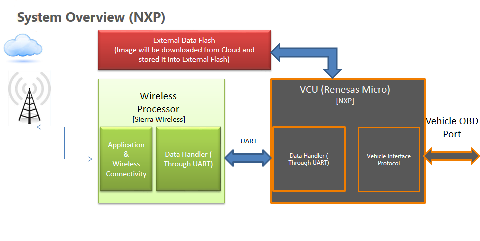
Communication is the backbone of any telematics devices inside a vehicle. Our customer had developed a state-of-the art telematics system to enable fleet management. However, the in-vehicle communication part was posing a challenge.

As the telematics system was designed for both passenger and commercial vehicles, several in-vehicle communication protocols were required to be implemented in the telematics ECU.

Further, the system also had to support older commercial vehicles that used almost obsolete communication protocols.

Developing all these proprietary protocol stacks required a dedicated team with specialized skills, as well as a number of licenses to be bought.

Getting in touch with a technology partner with ready-to-integrate protocol solution would not only reduce the cost but also ensure that the time-to-market is reduced considerably.

And that’s how this collaboration shaped up.
 

Embitel Solution

Following a series of discussions with the tech team of our customer, a list of communication protocols to be integrated was prepared.

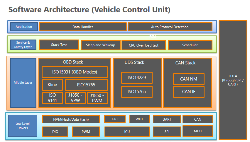
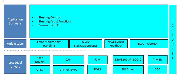
Following protocol solutions were configured and integrated with the telematics platform:

  • CAN2.0 250/500
  • SAE J1939
  • SAE J1587 / J1708
  • Single Wire CAN2
  • Low Speed CAN2
  • K-Line
  • ISO9141
  • CAN FD
  • Unified Diagnostic System (ISO 14229)
  • TP2.0
  • Autoprotocol/ AutoBaud Detection
  • OBD Stack – CAN, Kline, ISO9141

Our library of pre-tested and ready-to-deploy automotive protocol solutions contains each of these stacks. The task at hand for the engineers was to configure these stacks based on the requirements of the project.

We performed the configuration of the PGNs, CAN messages and other services required for the telematics system to communicate with vehicle ECUs and devices outside of the vehicle.

For instance, Classic CAN messages were configured to the SAE J1939 protocol software with the help of CAN IL tool.

*Our proprietary CAN IL tool automates the configuration process that would otherwise take weeks if performed manually. Result is lesser turn-around time and reduced chance of human error creeping into the configuration process.

Integration support with the Application Layer and the Low-level driver was provided to the customer.


Embitel Impact

Our team could save 6 months of man hours for our customers, courtesy our ready-to-deploy protocol solutions and the proprietary CAN IL configuration tool.

As the customer was aiming for a faster time-to-market, we were able to provide all the require support for the same.
 

Tools and Technologies

Freematics: It was used as an OBD simulator that helped our team perform the functional testing of the OBD stack before deployment.

CANoe from Vector: Helped us simulate the other automotive protocol stacks for verification

SAMTEC: Helped us simulate some older protocols like K-Line.

CAN IL Tool: Used to configure required CAN messages in SAE J1939 and other protocol solutions.


  • 0

Tessy Tool Powered Unit Testing of ISO 26262 Compliant Automotive Software


Our Customers:

We have had the opportunity to partner with some of the biggest automotive Tier-1 suppliers. The end customers of our partners are major OEMs.

Some of the Tessy Powered Unit Testing projects we worked on include ASIL C compliant Automotive Lighting Module, ASIL B compliant Pneumatic System, Powertrain ECUs and more.

We helped our customers with all the required work products for ISO 26262 Compliance.
 

Business Context:

Safety has become the number one priority among the Automotive OEMs and Tier-1 suppliers. As per a project’s specifications, there are several industry safety standards that need to be complied with. And Unit Testing is one major aspect of this compliance.

Our customers often face challenges with ISO 26262 compliant unit testing. For both compliance and certifications, they require the test reports from ISO 26262 qualified Unit testing tool.

There are multiple code coverages including MC/DC that is mandatory for certain ASIL grades.

Safety critical Automotive Applications like powertrain ECU, Body Control Module, Electronic Power Steering, etc. require comprehensive testing as per the ISO 26262 guidelines specified in Part-6 and Part-8.

The Test Reports from ISO 26262 qualified testing tools are sought by the ISO 26262 certifying authorities as evidence.

We have been technology partners to our customers for carrying out automated unit testing and report generation.

And Tessy, being one of the most reliable ISO 26262 qualified tool for unit testing, has been our tool of choice.

Following Test Methods and Test coverages were expected to be fulfilled.

software unit level
Software unit testing

Work-flow of our Unit Testing Methodology

Unit Testing Methodology
  • Tools like DOORS, Polarion help in Requirement Management.
  • Test Cases are prepared within the Classification Tree Editor (CTE) based on the requirement document.
  • Test Cases are reviewed, and a review report is generated.
  • Test Cases are executed in an automated manner.
  • Test Result is recorded and analyzed
  • Code Coverage is analyzed
  • The Test Report is provided as deliverable to the customer
  • Customer updates the code as per the bug report


Embitel’s Solution for Unit Testing Using Tessy Tool:

Approach 1 of Unit Testing

Tessy Tool
  • The default GNU GCC compiler will be used to do the compilation.
  • Test Report is generated for each of the software modules and its functions.
  • The Report is shared with the customer to help them rectify the code.

Approach 2 of Unit Testing

Unit Testing Tessy
  • An external Compiler and Debugger will be configured to the Tessy Environment.
  • We have worked on compilers including GHS Green Hills Compiler, Tasking compiler (Tricore V6.3).
  • Test Report is generated for each of the software modules and its functions.
  • The Report is shared with the customer to help them rectify the code.


Tools and Technologies:

  • Tessy Tool: For Automated Unit Testing of Software Modules.
  • Tasking Compiler: Used for code compilation and debugging.
  • Lauterbach Debugger: For code debugging; supports multiple Microcontroller Platforms.


  • 0

Development of ASIL Compliant Secure Bootloader for Automotive Tier-1 Customers


Business Context

ECU Reprogramming capability is one of the pre-requisites of an automotive control unit. And Flash Bootloader is the piece of software that makes it possible.

With control units getting more safety critical, the security of the data to be flashed on to these ECUs assumes much importance.

Automotive Suppliers and OEMs developing applications like ADAS, Telematics, Body Control Modules, etc. require flash Bootloaders equipped with security features such as Digital Signature, Encryption, HMS and others.

ISO 26262 standard also has certain guidelines regarding the security aspect of the Flash Bootloader.

We have been technology partners to several customers who are developing ISO 26262 complaint applications.

Embitel, as one of the leading technology vendors for automotive suppliers and OEMs, has partnered with many customers for the development of such ASIL compliant secure bootloaders.
 

About the Secure Bootloader Solution

Our Secure Bootloader solution is equipped with five security components- AES-128, Digital Signature, CRC32, HMS Drivers, Secondary Bootloader (SBL). These components ensure that the inter-ECU data transmission is secure and data integrity is not compromised.

Secure Bootloader Solution Overview:

  1. Cyber Security: It is implemented as per the customer’s requirement as well as the ASIL grade assigned to the project. For one of our customers, we have used AES 128 algorithm for encryption/decryption of the image file. Data is secured using the AES 128 algorithm before sending it to the ECU from the flashing device.
  2. Secondary Bootloader (SBL): Our Flash Bootloader secured with the help of Secondary Bootloader follows the following sequence:
    • A Secondary Bootloader with the Flash driver (A small binary file) gets downloaded to the Bootloader’s RAM.
    • Read and Write function is performed by the Bootloader to flash the ECU.
    • After the re-programming is completed, the flash driver is deleted from the RAM of the Bootloader

    As per the ISO 26262 standard, Flash Driver, which is responsible for read/write/erase, is implemented outside the Flash Bootloader software. This is a safety mechanism implemented to prevent unintended writing/erasing of the data.

  3. Digital Signature: Our secure Bootloader solution uses SHA 256 Algorithm for Digital Signature. Depending on the project’s requirements, we have also used AES 128 and other algorithms for the purpose. When secured with Digital Signature, the Bootloader uses SHA-256 algorithm to 256 bits image of the update data. The automotive ECU validates this digital signature before downloading the image file for ECU flashing.
  4. CRC32: Data Integrity is validated using CRC32 that is an error detecting code which is part of the Base Software of the Bootloader solution. If there is a corruption in the data while ECU flashing, it will be identified by CRC32. In such an instance of corruption, the data will not be accepted by the ECU and will be notified to the flashing tool.
  5. Hardware Security Module: Some microcontrollers come with built-in HSM module that implements security for the Bootloader. We developed the HSM device driver for the Bootloader Software to access the HSM module of the microcontroller. HSM also works with the AES algorithm in order to implement secure Bootloader.

We have the expertise to develop the device driver for the HSM module for different MCU families like NXP, Atmel, Infineon, Texas Instrument, Renesas, Cypress, ST Micro, Fujitsu, Microchip, Silabs and more.
 

Value-Adds of our Secure Bootloader Solution

  • No loss of data during ECU Flashing
  • Completely secure bootloader that cannot be hacked
  • 100% Image Validation is achieved
  • ISO 26262 compliant Secure Bootloader
  • Readily available components with project-specific configuration and device driver development


Tools and Technologies

  • Microcontroller– Infineon, NXP, Atmel, Microchip, Texas Instrument and more
  • Tasking Compiler: Used for code compilation and debugging
  • VFlash: Tool for ECU reprogramming

  • 0

Integration of Firmware-Over-The-Air (FOTA) Update with Industrial Battery Monitoring System


About the Customer:

Our customer is an OEM of photovoltaic inverters, variable frequency drivers and advanced automation systems for Industry 4.0. They are a trusted brand with focus on delivering innovative solutions for industrial automation systems.
 

Business Challenge:

  • The customer had deployed a network of industrial UPS solutions for several of their enterprise customers. Their battery management solution has been designed to monitor and report anomalies associated with battery discharge.
  • In the absence of any automation solution, field technicians were required to have expertise in examining the system, isolating the defective battery and identifying the defect in the battery.
  • The customer desired to implement an intelligent battery monitoring system that would ease the manual monitoring process and deliver benefits of Predictive Maintenance (PdM) or Proactive Maintenance.


Embitel Solution:

We developed the hardware and firmware for an industrial grade network of sensors for battery monitoring and data collection.

FOTA Update Integration


  • A Battery Monitoring Unit has been designed to collect voltage and temperature data from the installed batteries.
  • The data from multiple Battery Monitoring Units is transmitted to an IoT Gateway Device for analysis and decision making. This device constantly monitors the state and health of the batteries and alerts a technician by predicting the occurrence of a fault.
  • This solution is able to proactively identify discharged batteries in the network and inform an administrator when there was a need to take action.
  • The IoT Gateway Device is connected to two interfaces:
    • Field-deployed battery monitoring system
    • On-premise server or cloud server
  • The health and state of the batteries can be monitored through a mobile interface or web application that connects to the server and receives data from the IoT Gateway Device.

Integration of Firmware-Over-The-Air (FOTA) Update Feature:

In the event of a change in requirements (such as an alteration in battery voltage, an updated calibration algorithm, etc.) there would be a need to update the firmware in the IoT Gateway Device and the Battery Monitoring Units.

Since the setup was connected to a live high-power circuit, the activity of the entire plant will have to be ceased for manually updating the firmware.

Hence, the Battery Monitoring Unit and IoT Gateway Devices were developed to be reprogrammable over the air (FOTA).

How it Works

  • When required, FOTA Update Image is pushed to the cloud server by the admin users.
  • The cloud server then transmits FOTA Image to the IoT Gateway Device which, in turn, sends this information to the Battery Monitoring Units.
  • The Bootloader software ported in the Battery Monitoring Units initiates the re-boot of the system, downloads and integrates the updated firmware with the system.
  • Once the updates have been deployed, the status is sent back to the IoT Gateway Device that transmits it to the cloud.

Features

  • The hardware of the IoT Gateway Device and Battery Monitoring Units were configured such that it accounts for the additional memory required for storing FOTA images.
  • The bootloader software for each of these devices was specifically designed based on memory requirements for storing and updating the software.
  • If there is any disruption in the communication between the IoT Gateway Device and Battery Monitoring Units, the gateway device reinitiates the communication through multiple retrials.
  • The IoT Gateway Device and Battery Monitoring Units are equipped with the information to check the sanity of the images. This is a crucial step to ensure that the images are being received from authentic sources.
  • The system also performs CRC check to determine whether the received packet is complete. This helps in avoiding a partial firmware update.
  • The system has been incorporated with a rollback mechanism that is triggered in the event of failures. For instance, if there was a disruption in the WiFi network at the time of an update, the system rolls back to the default image and relinquishes the new update.


Embitel Impact:

  • The network of Battery Monitoring Units and IoT Gateway Device mitigates the complexities involved in the examination and assessment of the battery monitoring system for faults and failures. Hence, our solution reduces the operational cost by a significant amount.
  • Our solution enables the administrator to analyse whether the target voltage and current are maintained in the circuit. This overall view was not available in the original setup.
  • The network notifies the administrator of faults before the entire system shuts down due to failure. This is, hence, a Predictive Maintenance (PdM) solution for the battery monitoring unit.
  • In case there is a change in the measurement algorithm, there will be updates to the Battery Monitoring Units and IoT Gateway Device through FOTA.


Tools and Technologies:

  • Texas Instrument (TI) Industrial Microcontroller was used in the gateway device and battery monitoring units.
  • Texas Instruments (TI) FreeRTOS was used for embedded software development.
  • OrCAD design tools were used for schematic development. HyperLynx was used for Signal Integrity analysis, Power Integrity check, and Thermal Analysis.
  • Texas Instruments Code Composer Studio was utilised for the development of the gateway device and battery monitoring units.
  • QT framework was used for HMI design of the PC-Application and ATS.
  • TCP/IP server was used for remote PC configuration.
  • ModBus slave stack was utilised for creating an interface with the Building Management Software.

  • 0

AUTOSAR Software for an Ambient Lighting ECU and Integration of UDS Protocol Stack


About the Customer:

Our customer is a Tier 1 Supplier of Lighting Technology and one of the largest retailers of the automotive parts.

The three  primary product lines of our customer include Concept Lighting, Engine Management Systems (EMS) & Electronic Control Units (ECU) for the automotive.


Business Challenge:

Our customer had embarked on the journey of developing a next-generation Automotive Ambient Lighting product for one of the OEMs’.

This product line required development of an Auxiliary Lighting Module (ALM) Control Unit (ECU).

To design and develop this ALM Control Unit (ECU), our customer was looking to partner with a Product Engineering Services provider who can offer the following expertise:

  • Production-grade, ready-to-deploy and Industry-proven UDS (ISO 14230) Protocol Stack
  • Expert team who can support with the customization and the integration of the UDS Protocol stack
  • Expertise in Application Layer development for the Auxiliary Lighting Module ECU
  • Expertise in AUTOSAR Architecture (AUTOSAR MCAL, RTE and BSW)
  • In-depth understanding and product development expertise w.r.t CAN and LIN Interfaces

After the initial workshop discussions with our Software Development teams and also witnessing the demo of our production-grade UDS Protocol Stack; the customer had no hesitation in partnering with Embitel for the design and development of software for the Auxiliary Lighting Module (ALM) ECU.

Our teams had all the necessary software development (AUTOSAR) and tool-chain related experience and expertise.

Also, since we have had a successful partnership with the same customer for a Hardware Reverse Engineering Services Project in the past, the customer has had a first-hand experience of Embitel’s passion for quality delivery.


Embitel’s Solution:

The Solution Architecture:

AUTOSAR Compliant Software development
  • Auxiliary Lighting Module or ALM is an Electronic Control Unit which is designed to control functions like the light color as well as the intensity, to turn ON/OFF the sequence of Auxiliary Lighting Units or ALUs’
  • There can be multiple ALUs connected to a single ALM, as depicted in this diagram.
  • Each ALU had been designed to control individual lamp assemblies of the ambient lighting system.
  • Each ALU was required to communicate with the main ALM ECU through the LIN communication protocol interface.

The Solution (AUTOSAR Compliant Application Layer, Hardware Platform Software, CAN/LIN Interfaces, UDS Protocol Stack):

  • Compliance with AUTOSAR Architecture was a key consideration for the customer because they wanted to develop a modular solution architecture . This ensured a lot of business value-add for the customer.
  • Our expertise in the Vector Davinci toolchain made sure that we developed a robust AUTOSAR complaint Application Layer.
  • Our team executed the Unit Testing of the software using Tessy environment
  • Validation testing was done through CAPL Scripting. It was completely automated so as to allow us to test the responsiveness of the ambient lighting.
  • Our expert team designed the Hardware Platform Software consisting of Base Software, Handlers, Low Level Drivers, and UDS based Flash Bootloader Software was reprogramming
  • Our one-time licensing fee model for the production-grade UDS Protocol (ISO 14230) Software Stack, ensured that the customer enjoyed the value-adds of access to the source-code and the IP rights.


Embitel’s Impact:

Having all required capabilities in one place in addition to having the Tessy environment ready and a strong CAPL Scripting team in-house, our team was able to deliver a quality solution to the.

We could utilize several of our reusable components (like UDS Protocol Stack, Low-Level Device Drivers) to reduce the overall time needed to complete the software development.


Tools and Technologies:

  • Davinci Developer and Configuration
  • Microcontroller: Renesas RH850
  • Compiler: GHS
  • Test Environment: Tessy
  • CAPL scripting

  • 0

Firmware Over-the-Air (FOTA) Update and Bootloader Development for an Electric Vehicle


About the customer

Our customer is a leading Electric Vehicle OEM. Before this project, we have had the privilege of partnering with the same customer for other product development programs, mostly in the EV space.


Business Challenge

During the design stage, our customer realized the need for remote vehicle diagnostics and ECU re-programming for an Electric Vehicle Control Unit (ECU) product.

Integration of Firmware-Over-The-Air (FOTA) software and hardware could facilitate this requirement. Fully aware of our competencies, the customer was confident to partner with us for this FOTA project

After a series of discussions, it was agreed to develop a FOTA system with two microcontroller platforms – one for interfacing with the cloud backend to download the new update package and the other for interfacing with vehicle control units over CAN to fetch vehicle related data.

This complex system was to be built within a very challenging time frame. As we had already had several ready-to-deploy stacks- UDS, CAN, BSPs etc. as well as all the requisite skill sets, we had the confidence of delivering quality products within the stipulated time-frame.


Embitel Solution

After finalizing the project scope, our automotive software development team swung into action. The software architecture was prepared with clearly defined layers.

FOTA_System_Architecture_Case Study

Following were the deliverables we planned to provide:

  • FOTA enabled Bootloader to be implemented into the Application Processor (Sierra Wireless),
  • Bootloader software for a separate microcontroller called the Vehicle Control Unit (NXP),
  • Hardware Abstraction Layer (HAL), CAN/LIN drivers ( to facilitate communication between vehicle ECUs ),
  • HTTPS, MQQT protocol implementation (for secure connection with the cloud backend),
  • Low-level device drivers (SPI, UART, timer etc),
  • GPS & GSM modules and external memory module,
  • UDS software stack for remote vehicle diagnostics,

Here is an overview of the FoTA system we developed:

FOTA_Diagram_ME_Electric Vehicle

Our experience in working on a plethora of microcontroller platforms like Freescale, Renesas etc. ensured that we had reusable Board Support Packages and device drivers ready for deployment.

We performed the required customizations in these components, for seamless integration with Electric Vehicle ECUs. As agreed-upon, we also provided post-delivery support in the event of production environment issues.


Embitel’s Impact

The biggest impact was the reduced time-to-market, as this was a major concern for the customer.  We were able to deliver the project in 4 weeks.

Our reusable stacks and software packages were able to reduce the development time by a whopping 60%.


Tools and Technologies

  • Server for testing- Microsoft Cloud
  • IDE- Code Warrior and IR Embedded Workbench


  • 0

Development of AIS 140 Compliant FOTA Enabled Bootloader Module for a Tier-1 Supplier

About the Customer


Our customer is an Automotive Tier-1 supplier, specializing in vehicle control systems and components.

Keeping up with their commitment of delivering innovative solutions for the automotive industry, they planned to introduce FOTA (Firmware Over-The-Air) update feature in their product lines.

The basic idea was to enable the automotive control units to install software updates from the Cloud Server in real time. Eventually, the customer also wanted the product to be AIS 140 compliant.

Business Challenge


Customer’s project roadmap, of integrating FOTA in an Automotive Electronic Control Unit (ECU), was confronted with following challenges:

  • need for a robust FoTA enabled Bootloader solution
  • lack of expertise and experience in AIS 140

A CAN/LIN based Bootloader  was required for application and ECU reprogramming over the air.

The bootloader was required to be a part of the telematics unit that is tasked with ECU reprogramming over the air and facilitating remote vehicle diagnostics. The expertise in application processes development and testing for FoTA was also required.

A Product Engineering Services partner with ready-to-use components like Board Support Package (BSP) software and low-level device drivers for popular Microcontroller family was sought by the customer.

Having 12+ years of experience in CAN, Bootloader, and vehicle diagnostics, Embitel was chosen to come on-board for this project.

Embitel Solution


Before embarking on the solution development, we had several rounds of discussion to understand the pain points of the customers. We also analyzed the components that would need to be built from ground zero and found out opportunities where our re-usable components could be integrated.

The system architecture for the enablement of FOTA included the following components:

  • Telematics Control Unit,
  • Vehicle control unit,
  • Bootloader for telematics and MCU,
  • low-level device drivers,
  • and the Application Layer.

Our solution comprised:

  1. Telematics Unit (Renesas) to connect to the server using HTTPS and MQQT protocol
  2. CAN/LIN based Bootloader to flash the vehicle ECU
  3. CAN/LIN drivers to help the vechicle control unit collect data such as engine speed, vehicle parameters etc. from vehicle interface
  4. Low-level device drivers, SPI and UART drivers to facilitate communication between telematics unit and microcontroller.
  5. Remote diagnostics with UDS
  6. Application processor from Telit and Sierra Wireless with GPS and GSM modules for remote server connection; external memory for storing the update.

Apart from them, we deployed our production grade reusable components such as Board Support Package (BSP) software with flash drivers for Renesas Micro and Freescale MCU family.

Rigorous testing was performed on both internal servers and servers provided by the customer. We ensured that the components are AIS 140 compliant, as defined in the project scope. Post-delivery support was also provided by our team.

Embitel Impact


We were able to deliver the project in a very restricted timeframe. Our expertise in providing assistance for AIS 140 compliance was a great value add for the customer.

  • 60% of development time was reduced due to our reusable board support package and flash drivers.
  • Project was delivered in 4 weeks.

Tools and Technologies


Server for testing- Microsoft Cloud

IDE- Need to confirm with Suresh; will update


  • 0

Motor Controller Software, HAL and UDS Protocol Stack Integration for an Autonomous Headlamp

About the Customer:


Our customer is a leading manufacturer of Headlamp systems for Automotive. They have partnered with us as their Product Engineering Services provider, for prototype development of one of their ambitious Smart Automotive Headlamp product.

This Automotive Headlamp design facilitated the change in position of the Car Headlamps, with the help of sensors and motor control systems, based on the load and the elevation of the road.

Business Challenge:


Our customer is a pioneer in making Electric Headlamps for Automobiles.

However, for this next generation product development they realized the need for an experienced Product Engineering partner. The required skill sets comprised Embedded C, Device Driver development and comprehensive automotive domain knowledge.

Our Automotive team was tasked to design software algorithms that will enable headlamps to adjust automatically & focus in the right direction, based on the different states of the vehicle.

Embitel Solution:


After several rounds of discussion with the customer, the project scope was defined. Based on the discussion and our understanding of the project, we decided to develop our design based on NXP 32 bit microcontroller platform.

Getting the accurate pulse width modulation signal required algorithms to read the sensor data very precisely. Readings like the tilting angle and position from the sensors such as accelerometer and gyroscope also had to be analyzed.

Apart from the application layer (headlamp adjustment algorithms), low level device drivers and Hardware abstraction layer, were also designed. Their role was to facilitate communication between the servomotor and the application software.

We delivered a re-programmable unit which could be calibrated as per the production program.

Following is the software architecture diagram:

The final solution comprised:

Application software Development for autonomous electronic headlamp system:

  • Angular Velocity Algorithm for Pitch Calculation.
  • Level Controller- the motor drive algorithm that would drive the servomotor with pulse width modulation, PWM signals.
  • Parameter Configurations.
  • Self-Diagnostics to help the system find issues and report them.

Low level Device Drivers development:

  • Micro controller Unit.
  • Timer.
  • CAN drivers.
  • Pulse Width Modulation drivers.
  • Serial Peripheral Interface drivers.
  • Analog to Digital Converter.
  • Watch dog driver.
  • Non Volatile Memory (ROM).

Hardware Abstraction Layer:

  • CAN Interface.
  • Pulse Width Modulation HAL.
  • Serial Peripheral Interface HAL.
  • Analog to Digital Converter HAL.

Service and Diagnostics Layer:

  • Math utility (Filtering, Average etc.).
  • Safety features (CPU Overload, Stack over flow).
  • Scheduler (Non preemptive timer based).
  • UDS based Diagnostics Layer (ISO14229) & ISOTP (ISO15765).
  • Fault Code Memory (FCM).

Apart from the application software and device drivers, the deliverables also included:

  • Low-level documents.
  • High-level documents.
  • Test Plans and Reports.
  • Our Ready-to-deploy UDS based bootloader software for ECU reprogramming purposes.

Impact


We were able to provide the complete set of deliverables within the stipulated time. We integrated our ready to-deploy Bootloader software and UDS stack with the production grade prototype. This helped us reduce the development time and cost.

Our experience in working with motor control systems also came in handy while developing the leveler algorithms for the project.

Tools and Technologies Used


S32 IDE from NXP – For embedded C programming.

PE Debugger- For code debugging.

SCANoe–– For CAN Testing

BUSMASTER–Testing.

Motor– Servomotor for precise movement based on angular/linear position.


  • 0

Motor Control Hardware and Software Development for an Electronic Power Steering (EPS) System

About the Customer


Our customer is a Europe based Tier-1 supplier of automotive steering and driveline solutions.

They were searching for an experienced Product Engineering partner for Proof-of-Concept (complete hardware and software solution) development, for one of their ambitious Electronic Power Steering (EPS) solution.

Business Challenge


There was a limited time frame for developing the complete hardware and software components of the electronic power steering and also validate it on the test-bench created by the OEM.

On top of that, the system was supposed to be ISO 26262 ASIL D compliant. This required expertise in creating safety plans and to follow the complete safety lifecycle as mandated by ISO 26262 standard.

Moreover, the need for integration with software stacks like J1939, was also felt to manage the communication with automotive ECU.

Since we had a ready-to-deploy J1939 stack solution, we were confident of adding value to this project by reducing the time-to-market

The customer also evaluated our expertise in motor controller development. By the virtue of our experience and skill-sets, we were on-board for this proof-of-concept development of EPS ECU.

However, the customer encountered a major roadblock during software porting.Due to limited on-chip memory (RAM and ROM) of DsPIC 30F4011 platform, it became imperative for the customer to port highly-optimized embedded software to the EPS system.

Re-designing or changing the hardware platform would have impacted the bottomline of the project negatively, leading to substantial financial loss. Also, the DsPIC Microchip platform was best suited for the required EPS application, meaning that the only feasible resolution was an Optimized Embedded Software.

Embitel’s Solution


After a few rounds of discussion with the customer’s automotive steering and driveline solutions team, it was decided that MPC5643L dual core micro controller will be best suited hardware platform for this project.

Our task was precisely cut-out, which was to develop the complete vehicle ECU hardware and software solution for the EPS.

The first step was to develop the hardware using this microcontroller. Following components were developed and integrated with the system:

The customer also evaluated our expertise in motor controller development. By the virtue of our experience and skill-sets, we were on-board for this proof-of-concept development of EPS ECU.

ASIL D certified MPC5643L dual core micro controller

2 KW NIDEC Motor (Automotive Grade)

ASIL D Pre-driver Component– Controls the motor with integrated PWM; Regulates HALL sensors etc.

Gate Driver IC- Acts as power amplifier for MOSFETS; Also sends error feedback to the ECU in a closed loop system

Voltage measurement sensor- Measures the motor voltage and passes the info to the ECU as a feedback

H-Bridge Component– MOSFETs

Steering Angle and Toque Sensor– Measures the angle and torque on the steering

HALL Sensor Feedback– To measure RPM, Motor Speed etc and send the data to the ECU

Temperature Sensors- Measures the temperature and feeds the reading to the ECU. This facilitates shutting down of the motor at high temperature

Our team also partnered to develop low-level drivers, hardware abstraction libraries and the application software required for the hardware platform and the peripherals.

We also designed various software algorithms in order to support necessary Motor Control features and functionalities.

Here’s the complete list of software algorithms that were developed


Algorithms
   Steering Control– Assist factor algorithm; torque sensors value, and angle sensor provided as inputs to the steering assist function, by external hardware. This algorithm also fetches RPM value via CAN message.
  Motor Control– It is an algorithm that sets the motor speed based on the torque. It also interfaces with steering assist functions.
  Signal conditioners– They smoothen the pulse value from the hardware. The sensors will provide ECG like values that need to be conditioned. This is called signal conditioning. The value is given to the motor controller after signal conditioning.
  Sensor Drivers– ADC drivers are required for reading the values from the sensors
  Actuator Drivers– PWM- used to adjust the motor speed; Gate driver unit drivers
  J1939 Based Bootloader and Diagnostics: Ready-to-deploy stack for ECU communication and vehicle diagnostics
  Standard Core- Memory handling, EEPROM, Scheduler

We tested the software and hardware using various testing tools. We also collaborated with the customer for End-of-Line Testing.

We tested all the software and hardware components on the test bench provided by the customer.

Some of the issues faced during this process and how they were rectified

The major problem that was faced in the test-bench was a jerk in the steer wheel. We were not able to get the desired smoothness.

Based on the parameters, we identified the issue in the assist factor algorithm. Our automotive developers were able to fine-tune the algorithm to adjust the assist factor.

“A safety lifecycle for hardware and software development was running in parallel to ensure that the components are ISO26262 ASIL D compliant. A safety manager was assigned for this and was supported by different teams.”

Embitel’s Impact


We were successful in developing the POC in 3 months- the time period that we were given by the customer. This helped the customer develop a PoC of an ISO 26262 ASIL D Electronic Power Steering ECU in a short period of time.

We were able to accomplish the task due to the following reasons:

Our power steering system and software capabilities

Ready-to use Bootloader J1939 for diagnostics

Team of Motor Control Experts

Tools and Technologies Used


IDE- CodeWarrior

Vehicle Spy for CAN Signal Simulation

CANOe Analyser


  • 0

Motor Control Hardware and Software Development for an Electronic Power Steering (EPS) System

About the Customer:

Our customer is a Europe based Tier-1 supplier of automotive steering and driveline solutions.

They were searching for an experienced Product Engineering partner for Proof-of-Concept development, for one of their ambitious Electronic Power Steering solution.


Business Challenge:

There was a limited time frame for developing the complete hardware and software components of the electronic power steering and also validate it on the test-bench created by the OEM.

On top of that, the system was supposed to be ISO26262 ASIL-D compliant. This required expertise in creating safety plans and to follow the complete safety lifecycle as mandated by ISO26262 standard.

Moreover, the need for integration with software stacks like J1939, was also felt to manage the communication with automotive ECU. Since we had a ready-to-deploy J1939 stack solution, we were confident of adding value to this project by reducing the time-to-market.

The customer also evaluated our expertise in motor controller development. By the virtue of our experience and skill-sets, we were on-board for this proof-of-concept development of EPS ECU.


Embitel’s Solution:

After a few rounds of discussion with the customer’s automotive steering and driveline solutions team, it was decided that MPC5643L dual core micro controller will be best suited hardware platform for this project.

Our task was precisely cut-out, which was to develop the complete vehicle ECU hardware and software solution for the EPS.

The first step was to develop the hardware using this microcontroller. Following components were developed and integrated with the system:

  • ASIL-D certified MPC5643L dual core micro controller.
  • 2 KW NIDEC Motor (Automotive Grade).
  • ASIL-D Pre-driver Component– Controls the motor with integrated PWM; Regulates HALL sensors etc.
  • Gate Driver IC- Acts as power amplifier for MOSFETS; Also sends error feedback to the ECU in a closed loop system.
  • H-Bridge Component– MOSFETs.
  • Steering Angle and Toque Sensor– Measures the angle and torque on the steering.
  • HALL Sensor Feedback– To measure RPM, Motor Speed etc and send the data to the ECU.
  • Temperature Sensors- Measures the temperature and feeds the reading to the ECU. This facilitates shutting down of the motor at high temperature.
  • Voltage measurement sensor- Measures the motor voltage and passes the info to the ECU as a feedback.

Our team also partnered to develop low-level drivers, hardware abstraction libraries and the application software required for the hardware platform and the peripherals.

We also designed various software algorithms in order to support necessary Motor Control features and functionalities.

EPS Motor Control Unit

Software Block Diagram of an EPS Motor Control Unit.
Here’s the complete list of software algorithms that were developed:

  • Steering Control– Assist factor algorithm; torque sensors value, and angle sensor provided as inputs to the steering assist function, by external hardware. This algorithm also fetches RPM value via CAN message.
  • Motor Control– It is an algorithm that sets the motor speed based on the torque. It also interfaces with steering assist functions.
  • Signal conditioners– They smoothen the pulse value from the hardware. The sensors will provide ECG like values that need to be conditioned. This is called signal conditioning.  The value is given to the motor controller after signal conditioning.
  • Sensor Drivers– ADC drivers are required for reading the values from the sensors.
  • Actuator Drivers– PWM- used to adjust the motor speed; Gate driver unit drivers.
  • J1939 Based Bootloader and Diagnostics: Ready-to-deploy stack for ECU communication and vehicle diagnostics.
  • Standard Core- Memory handling, EEPROM, Scheduler.


We tested the software and hardware using various testing tools.  We also collaborated with the customer for End-of-Line Testing. We tested all the software and hardware components on the test bench provided by the customer.
Some of the issues faced during this process and how they were rectified:

The major problem that was faced in the test-bench was a jerk in the steer wheel. We were not able to get the desired smoothness.

Based on the parameters, we identified the issue in the assist factor algorithm. Our automotive developers were able to fine-tune the algorithm to adjust the assist factor.

“A safety lifecycle for hardware and software development was running in parallel to ensure that the components are ISO26262 ASIL-D compliant. A safety manager was assigned for this and was supported by different teams.”


Embitel’s Impact:

We were successful in developing the POC in 3 months- the time period that we were given by the customer. This helped the customer develop a PoC of an ISO26262 ASIL-D Electronic Power Steering ECU in a short period of time.

We were able to accomplish the task due to the following reasons:

  • Our power steering system and software capabilities.
  • Ready-to use Bootloader J1939 for diagnostics.
  • Team of Motor Control Experts.


Tools and Technologies Used:

  • IDE- CodeWarrior.
  • Vehicle Spy for CAN Signal Simulation.
  • CANOe Analyser.