×

Happy to Help!

This website doesn't store cookies. Enjoy the experience, without worrying about your data!

Great, thanks!

Category Archives: Modeling & Simulation

  • 0

Development of ASPICE Level 2 Automotive In-Cabin Air Quality Purification ECU

About the Customer

Our customer is a leading automotive tier-1 supplier with a focus on delivering cutting-edge solutions for air quality improvement in vehicles. With a commitment to sustainability and passenger well-being, the customer plays a crucial role in enhancing the in-cabin experience for automotive manufacturers worldwide.

Business Challenge

The customer had successfully designed and manufactured all the mechanical components required to build an advanced in-cabin air purification system.

However, they faced a critical challenge in providing and maintaining a stable voltage supply to power the purification system effectively.

To ensure optimal performance, the air purification system required a closed-loop control mechanism managed by a Microcontroller Unit (MCU). The optimum voltage could be achieved and maintained by PWM signals generated using the ECU.

In a nutshell, the requirement was to build an air purification ECU with the required hardware and software. Since the system was intended to be designed for automotive use-cases, ASPICE Level 2 compliance was required.
 

Embitel’s Solution

Embitel’s expert engineering team collaborated closely with the customer to develop a comprehensive and efficient solution for their cabin air purification system.

The solution involved the development and testing of hardware components and various software layers and applications based on customer specifications. Our ASPICE compliance team was taken on-board for continuous assessment and audit as per ASPICE L2.

After the projects milestones were established, the hardware and software teams began to jointly develop the air purification ECU.


A Snapshot of ASPICE Level 2 Compliant Hardware Development and Testing

Embitel’s hardware development for the Automotive Cabin Air Purification System project followed ASPICE L2 guidelines, ensuring a systematic and robust approach to deliver high-quality hardware components. The ECU was responsible for processing data from various sensors, controlling the purification process, and interacting with the software components.

The hardware development process included the following key stages:

  • Hardware Schematic Design for ECU
  • A detailed hardware schematic was meticulously designed, considering the system requirements, component specifications, and ASPICE L2 guidelines

  • Simulation Tests
  • Prior to physical board fabrication, the hardware team conducted extensive simulation tests using advanced simulation tools.

  • Board Bring Up and Module Testing
  • In the board bring-up stage, the newly assembled ECU boards were powered up and tested for basic functionality and initial communication with other components. Module testing involved rigorous testing of the ECU’s individual functionalities and interfaces to verify their performance against specifications.

    In addition, Embitel conducted EMC/EMI testing to ensure that the ECU complied with relevant electromagnetic standards and did not interfere with other electronic systems in the vehicle.

Important Hardware Modules in the ECU

DC-DC converter: DC-DC converter was required for buck/boost. A high-voltage control was needed for air purification system to operate, and a low voltage DC-DC converter supplied lower voltage to the MCU.

Microcontroller: An automotive grade MCU was used to execute the algorithm for generating optimized PWM signal.

A Snapshot of Software Development of Air Purification ECU

The software part of the air purification ECU comprised of various layers including the application as well as the base software layer.

While traversing the requirement specifications, our automotive team realized that the application layer is quite complicated. And thus, model-based development approach was taken.

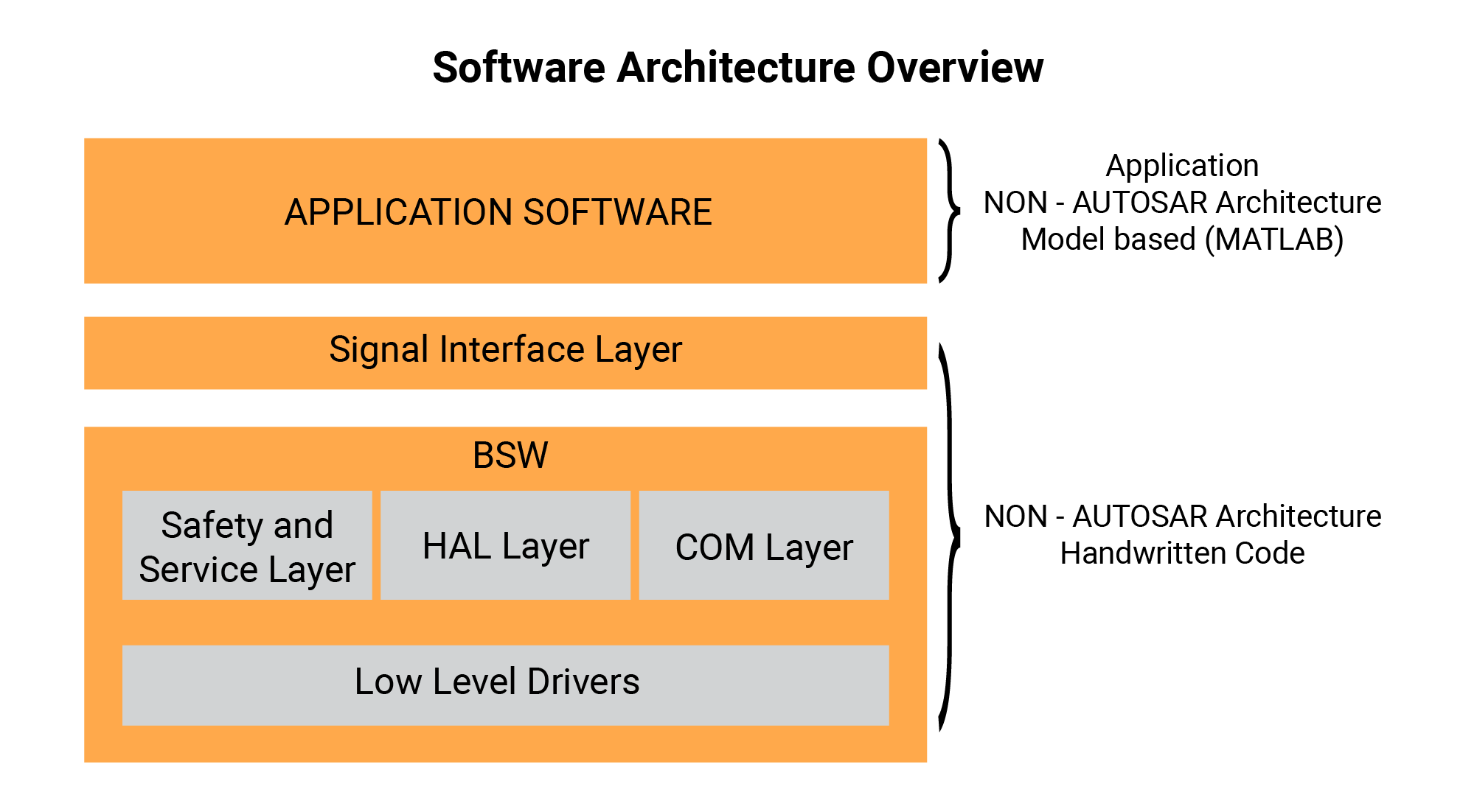
For base software, the team went with manual coding.

  • Model-based Development of Application Software Layer: The application layer encompassed a couple of applications developed based on customer specifications, including:
    • System Manager: Responsible for managing and coordinating various functionalities within the air purification system.
    • Application for Air Purification: Utilized pulse-width modulation (PWM) to generate an optimum voltage for air ionization, ensuring efficient air purification.
  • Low-level drivers: Comprised of watchdog timer (WDT), microcontroller driver, SPI, PWM, Code Flash, LIN slave drivers, etc.
  • Safety and service layer: Stack overflow driver, CPU overload detection algorithms, self-diagnostics, etc.
  • Development of COM layer: LIN based communication through our ready-to-integrate LIN protocol stack (LIN interface, Lin NM layer and LIN Transport layer).
  • UDS based Diagnostics Layer Implementation: UDS server stack implemented as per ISO 14229. UDS stack was configured as per the specifications and integrated with the ECU. UDS based bootloader was also implemented.

MISRA C 2012 compliance was achieved using tools like Polyspace.

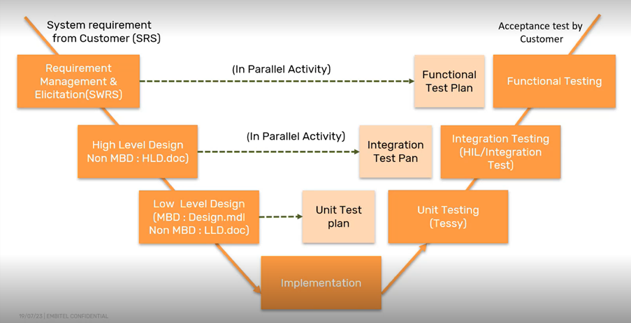
We also performed unit, integration, and functional testing for the modules.

Project Compliance with ASPICE L2

Our development of the Automotive Cabin Air Purification System adhered to the rigorous ASPICE Level 2 requirements.

Embitel’s Impact

Embitel’s expertise in developing new-age automotive solutions, particularly ASPICE-compliant solutions for cabin air quality improvement, had a profound impact on the success of the project.

Our library of reusable modules and a robust base software framework played a pivotal role in accelerating the development process.

Our ready-to-deploy LIN and UDS stacks further streamlined the development process by at least 6 months.

Tools and Technologies

  • NXP IDE – Code editing, compiling and debugging
  • Tessy – Unit and Integration testing
  • Polyspace – Static code analysis
  • SIMULINK – Model based development of application software

  • 0

Development of 4-Channel CAN Interface Layer Configuration Tool for an Automotive Tier-1 Supplier

About the Customer

Our customer is an Automotive Tier-1 supplier with continued focus on evolving software technologies related to battery management system, telematics and more.

Business Challenge

Automotive solutions that work on multiple CAN channels require dynamic configuration of the CAN interface layer using the CAN DBC files. While developing a similar solution, our customer’s team felt the need for a CAN IL tool with capability of simultaneous configuration of 4 CAN channels with different DBC files.

Performing this task manually would cause several issues such as:

  • Increased time to configure each CAN channel
  • Errors introduced by manual handling of CAN interface layer configuration file

Owing to these challenges, the development team of our customer decided to build an automated tool that could dynamically configure the desired CAN channels or all 4 of them in one go. The customer approached us with this challenge and as always, we were happy to help.
 

Embitel’s Solution

Developing a 4 channel CAN interface layer configuration tool was something new for us. In the past, we had developed auto configuration code generator tool, but this was different in many aspects. Our team rose to the challenge and first chose the development tool ideal for this solution which is Qt.

The development team built upon its experience of developing a single-channel tool and developed this Auto CAN IL tool. As per the requirements provided by the customer, this tool gives the option to choose the DBC file, select the CAN channel for configuration and even look into the tx and rx messages inside the DBC file.

Here’s a snapshot of the Auto CAN IL configuration tool:

CAN Interface Layer Configuration Tool

Salient Features of the Auto CAN interface layer configuration tool are:

  • 4 different DBC files can be chosen at one instance
  • Configuration files for all 4 CAN channels can be simultaneously generated
  • Network nodes inside the DBC files can be selected before the configuration
  • Schedule time, message queue size can be customized for each configuration

Along with the Auto CAN IL configuration tool, we also provided the High-level data document and unit and functional test reports and MISRA C compliance report.
 

Embitel’s Impact

The Auto CAN IL config tool single handedly reduces the configuration time by 4 times, considering only one CAN channel is configured at a given instance. On top it, the fact that 4 different DBCs can be configured solves the most difficult pain point for the customer of dynamic configuration of CAN interface layer.
 

Tools and Technologies

CAN IL configuration tool was developed using Qt, which is a cross-platform software for developing user interfaces and applications for embedded systems.


  • 0

MATLAB (Simulink) Based UI Development for Low Level Drivers of Model Based Application | Automotive Tier-I Supplier


Customer:

An US Tier-1 supplier of automotive and industrial products.


Business Challenge:

  • Our customer was engaged in a model based development project.
  • The customer identified the need for the development of a configurable interface for managing the settings of Low Level Drivers (LLD), Application Model functionality testing and code generation.


Embitel Solution:

  • Our Automotive software team developed the required User Interface (UI) in MATLAB, Simulink using s-functions and GUIDE.
  • The S-Function Interface, supported by the UI, is a solution to manage configuration/settings of the low-level drivers.
  • These Low level device drivers (LLD) had been manually coded to support functions of various blocks of the Model Based Application layer.
  • For code generation and testing of LLD, various block modules had been designed like signal conversion modules (for example ADC) , electrical signal control modules (example, current and voltage) and more
  • Each block (within the mentioned module) was assigned multiple S-Functions. We also developed UI screens for each S-Function, to support configuration of LLD settings.
  • For an instance, the communication protocol block has different UI message IDs for different functions such as configuring baud rates, transmit/receive channel and more. When the user selects a message ID from the UI, the supported scripts call the relevant LLD function. The LLD function loads the data requested by the user for further processing.
  • These s-function blocks are used for simulation testing (MIL) and are further used for code file generation once the simulation is successful.

S Function Architecture
 
Embitel Impact:

  • The stability and performance of the whole system (LLD configuration with the model based application) improved due to simulation testing in virtual environment.
  • Our automotive software development team, followed software development best practice and automated the whole process of s-function generation, model creation and code generation using tool and scripts.
  • To save the overall process time, our expert engineers automated some sub-steps required for block creation.
  • With minimal changes, these scripts are reusable across multiple MATLAB or Simulink projects.


Tools Used:

  • Matlab, Simulink 2015b
  • Windriver Compiler

  • 0

Model-Based Development of Seating Comfort System | US Based Tier-I Supplier


Customer:

Tier-1 supplier for automotive and industrial products.


Business Challenge:

  • During the Model Based Development of their latest Seating ECU, our customer was confronted with a unique challenge related to controller memory.
  • For this project, the customer created floating point library model which occupies a large part of on-chip memory, because of the ‘double’ data type.
  • Since this new Automotive Seating ECU featured some very advanced seating comfort and control functions, floating point library modeling turned out to be an inefficient method with respect to on-chip memory consumption
  • To resolve this issue within time and budget constraints, the customer was on a look out for an embedded software partner with in-depth expertise in Model Based Development.


Embitel Solution:

  • During the technology workshops, our automotive software development team and the customer agreed to convert the floating point models into fixed point models.
  • Since there were multiple blocks of models that required the conversion, our embedded software developers also started working on the automation tool to make the entire process more efficient.
  • Step-by-step details of migration to fixed point models:

    • The first step was to determine the data types of the signals and parameters for all the library models.
    • Then the model initialization files were created, containing all the signals and parameters with all their required attributes.
    • The fixed point models were created from provided floating point library models. Then, the optimized codes were generated.
    • We also created interface files for low-level driver.
    • Then, these MATLAB generated code files were integrated with the low-level drivers
  • Our automotive software team leveraged the in-house designed automation tool for all the future releases
  • Due to Automation of the whole process, the development time was reduced from several days to a 2-3 day process.
  • The tool ensured automation of the following steps:
    • Model Initialization file creation
    • Interface Files Creation
    • Fixed point code based Model creation
    • Code generation


Embitel Impact:

  • Our automotive software development team’s pro-active approach helped us to identify the scope of automation. This ensured reduction in the turnaround time for the new releases.
  • The automation tool reduced the overall process time by around 80% and has substantially improved the accuracy of the work products.
  • As per the client requirement, with minimal changes, the tool can be reused across multiple MATLAB/Simulink projects.


Tools used:

  • Matlab / Simulink 2013b
  • Matlab / Simulink 2016b
  • ERT coder
  • IAR compiler
  • CANoe

  • 0

Model Based Development of Body Control Units

Embitel uses model based development (MBD) to design and develop complex, control system based, automotive embedded systems. Embitel can support the complete ‘V cycle’ of model based development covering requirements, modeling and simulation, rapid prototyping, auto code generation, HIL, MIL and SIL testing.

Embitel offerings in this domain include:

  • Algorithm design, simulation using tools like Matlab / Simulink. ASCET & Labview
  • Modeling and simulation, autocode generation using RTW, Targetlink etc
  • Rapid prototyping with porting & optimization
  • MIL, SIL and HIL testing using ETAS, dSpace, Mathworks, MBTech, Opal-RT tool chains.

We have integrated our MBD and traditional manual coding approaches to design and develop turnkey solutions in the area of Body Control Units.

System Overview:

  • Model based development using Mathwork’s tool chain
  • End to End development from raw requirements to system testing
  • PIC microcontroller based ECUs
  • Followed MAAB guidelines for modeling
  • Code generation using RTW
  • Manual coding of low level software
  • Integration with low level software
  • CAN, LIN based networking
  • KWP2000, UDS based diagnostics
  • Boot loader for re-flashing
  • System testing