×

Happy to Help!

This website doesn't store cookies. Enjoy the experience, without worrying about your data!

Great, thanks!

Decoding the “Component Concept” of the Application Layer in AUTOSAR

  • 0

Decoding the “Component Concept” of the Application Layer in AUTOSAR

As you know, the AUTOSAR or AUtomotive Open System Architecture was  developed to create a common standardized software architecture for designing automotive electronic control units (ECUs). The AUTOSAR architecture is based on a 3-layered architecture model, developed jointly by the stakeholders of the automotive industry including – the automobile manufacturers, the suppliers, and the tool developers.

The 3-Layered AUTOSAR Architecture

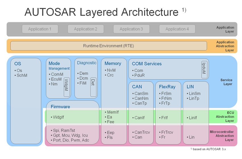
Let us have a quick look at the AUTOSAR software architecture. The AUTOSAR specifies a three-layer architecture, which are categorized into following modules:

  • Basic software (BSW): can be defined as standardized software module offering various services necessary to run the functional part of the upper software layer. This layer consists of the ECU specific modules along with the generic AUTOSAR modules.

    It is divided into three sub layers namely the Services layer, ECU (Electronic Control Unit) abstraction layer, and the Microcontroller Abstraction Layer (MCAL).

    The MCAL is a software module that abstracts all the upper layers ( the application layer and the BSW) Microcontroller. Thus, MCAL helps in making the upper layers independent of the low lying hardware platform.

  • Runtime environment (RTE): acts as a middleware between the AUTOSAR application layer and the lower layers. Basically, the RTE layer manages the inter- and intra-ECU communication between application layer components as well as between the BSW and the application layer.
  • Application layer: The AUTOSAR application layer includes various application specific software components that are designed to execute specific set of tasks, as per the use-case.

In this blog, we would be discussing about the AUTOSAR Application layer in detail.

1 AUTOSAR Archtecture

The 3-Layer AUTOSAR Software Architecture; Image Credit: researchgate

The Application Layer in AUTOSAR

The AUTOSAR Application layer constitutes the topmost layer within an AUTOSAR software architecture and is identified to be critical for all the vehicle applications. The AUTOSAR standard specifies the application layer implementation using a “component” concept.

While talking about the application layer implementation, three of the most important parts that should be considered are:

  • The AUTOSAR application software components
  • The AUTOSAR ports of these components
  • The AUTOSAR Port Interfaces

AUTOSAR application software components: A typical E2E(End to End) functionality includes many interconnected AUTOSAR Application Software Components (SW-C). The application software component constitutes the simplest form of an application with certain functionality. AUTOSAR defines standardized interfaces associated with all the application software components required to develop automotive applications.

These software components are connected with the help of well-defined ports. These ports facilitate communication between the software components as well as with the AUTOSAR BSW. In the context of the Application Software Components, there are certain entities called the Runnables, which are basically the  procedures that contain the actual implementation of the software components.

Runnable or Runnable Entities are defined within the VFB specifications and is part of an atomic software component (described in a later section). Runnable are defined as the smallest fragments of code or a sequence of instructions given by component and executed by RTE. A runnable entity is triggered either cyclically or during an event such as data reception.

AUTOSAR Software Component

Image: Depiction of a typical Software Component

An AUTOSAR SWC can be considered only as an atomic entity, this means that every instance of an AUTOSAR SWC is assigned to only one ECU and cannot be distributed across many ECUs.

Types of Software Components of  AUTOSAR Application Layer:

To understand the AUTOSAR software component in further detail, it is vital to look at  the various types in which AUTOSAR SW-Cs are available within the application layer

  1. Sensor/Actuator Software Component: A type of AUTOSAR Software Component for handling sensor evaluation and actuator control functions. This particular AUTOSAR Software Component depends on the associated sensor/actuator and is independent of the specific ECU, to which it is mapped to.
  2. Composite Software Component: A composite component offers a logical interconnection of other components, which could be either atomic or composite. These components are called prototypes and usually are not required to be deployed on the same ECU. Instead these can be distributed over several ECUs.
  3. Atomic Software Component: An atomic software component is the smallest form of software component that cannot be decomposed further into smaller units. And contrary to the composite type, an Atomic Software Component can be assigned to only one ECU.

The AUTOSAR ports: The AUTOSAR Software Components use well-defined ports, which encapsulate certain interfaces as a guarantee for type safety while components are communicating with each other.

A port is mapped to a single component and represents a communication point between the components.  This inter-component communication is managed by the Virtual Function Bus (VFB).

The AUTOSAR Interfaces:

As we discussed earlier, the AUTOSAR standard defines certain standardized interfaces for the application software components that are required to develop various automotive applications. This definition of the interfaces helps in obtaining the required functionality of the vehicle application.
In order to better define the communication of data or services through port of a typical component, the AUTOSAR introduced the Interface concept. The port interface required by an application software component serves as the input to the RTE port creation.  An AUTOSAR Interface is categorized into:

  1. Client-Server interface: This interface defines a set of operations that can be invoked based on the client-server pattern. Here the client initiates the communication, and requests the server to perform a service.

    The server performs the request service and sends a response to the request. The direction of the message initiation can be used to identify if the AUTOSAR Software Component is a client or a server. In the diagram below, the client the AUTOSAR SWCs, client 1 and 2 respectively , request a service through the RPorts ( Request Port) which is sent to the, the server AUTOSAR SWC which offers the required services through the PPort ( provider Port).

    AUTOSAR Communications

    Image: The client server communication between AUTOSAR software components.
  2. Sender-Receiver interface: This interface defines an asynchronous information distribution and allows for a more data-oriented information exchange over the virtual function bus.
  3. The decision related to what all information should be exchanged through sender-receiver communication and which of the services should be called by the client-server communication – are taken by the interface.

    Data Distribution

    Image: Data distribution through the sender-receiver interface type

Communication Between the Software Components ( SW-C)

During design time of an AUTOSAR application, the VFB is used to manage the communication between the software components. This virtual bus abstracts the applications from the infrastructure. VFB is an abstract component that is represented usually by the Runtime Environment (RTE) at the runtime, and generated uniquely for each ECU in the AUTOSAR system. The VFB connects the various SWCs in the design model .

The VFB communicates via dedicated ports, which means that the communication interfaces of the application software must be mapped to these ports. The VFB handles communication both within the individual ECU and between ECUs.

ECU Communication

Image: Types of communication between the SW-Cs; Image credit: techiscafe

The communications between the applications software component can be:

  • Inter-ECU. Or
  • Intra-ECU

as explained in the diagram above. Both the inter and intra-ECU communication between the application software components communication is managed through the RTE.

The interaction between ECU I and ECU II  is an example of inter-ECU communication and takes place through and beneath the RTE  and goes via the Basic Software Module. The BSW handles the functions like  interactions with the memory, diagnostics,  along with communication services ( if needed) for the inter-ECU communication.

The intra-ECU communication, that is the communication within the ECU between the software component B ( SW-C B) and the software component C (SW-C C ) , is entirely through the RTE.As evident from the diagram , the software components that are mapped to a single ECU use the Intra-ECU method.

The Role of RTE: The implementation of the AUTOSAR software components is made independent of available communication mechanisms by the RTE by offering a uniform environment to these to AUTOSAR Software Components ( SWC).

Application layer exchanges data with the underlying layers via the sender and receiver ports of the RTE. Whenever an AUTOSAR software component calls for the service objects, the RTE maps these requests to the actual service object symbols on the local ECU.

The Complex Device Driver Exception – offering direct access to hardware

As the layered nature of the AUTOSAR software architecture does not allow direct access of the hardware by the upper layers, an additional concept was needed to bypass this restriction especially for the resource critical and/or Non-AUTOSAR compliant software components.

And it is here that the Complex Device Driver comes into scenario. The Complex Device Driver basically offers an AUTOSAR Interface to the application layer and thus gains direct access to values on the physical layer.

The concept of Complex driver is useful for application components that call for a direct access to the hardware devices on the ECU. Injection control or electronic valve control applications are good examples of such applications that require direct access to the hardware.

If we look at the AUTOSAR application layer implementation process, it is a function of the AUTOSAR Software Component which is independent of:

  1. The type of Microcontroller of the ECU being mapped.
  2. Type of ECU being mapped
  3. The location of the AUTOSAR Software Component
  4. The number of times a software component is instantiated within the system or an ECU.

The application software implementation within the AUTOSAR is encapsulated within the software components and forms the core of the AUTOSAR application implementation process.


  • 0

What is AUTOSAR Memory Stack | Software modules and device drivers

This blog is part of a series of articles to help you learn about layered architecture of AUTOSAR.

Through this article our AUTOSAR development team, which is based in Bangalore, India, has tried to share knowledge with the community of AUTOSAR developers and automotive OEMS and Suppliers.

In this blog we will introduce you to AUTOSAR Memory Stack (MemStack). This will help you understand the software modules and device drivers associated with Memory Stack.

Introduction: AUTOSAR Memory Stack (MemStack):

Memory Stack (MemStack) provides basic memory management services to the upper Application layer and to the Basic Software Modules (BSW) of the AUTOSAR layered architecture.

The memory management services ensure access to the memory cluster, to the devices or software functions, for reading and writing data to non-volatile memory media like Flash or EEPROM

The following block diagram show various software modules and device drivers associated with AUTOSAR Memory Stack:

autosar-memory-stack

(Source – ARC CORE)


Software Modules and Device Drivers – AUTOSAR MemStack

Memory Stack in AUTOSAR layered architecture is a collection of software modules and device drivers.

Following is the list of modules in different layers of AUTOSAR:

  • Non-Volatile Memory Manager (NvM) – it is part of the AUTOSAR Services Layer
  • Memory Interface (MemIf) – it is part of the AUTOSAR ECU Abstraction Layer
  • Flash EEPROM Emulation (Fee) – it is part of the AUTOSAR ECU Abstraction Layer
  • EEPROM Abstraction (Ea) – it is part of the AUTOSAR ECU Abstraction Layer
  • Flash Driver (Fls) – it is part of the AUTOSAR MCAL Layer
  • EEPROM Driver (Eep) – it is part of the AUTOSAR MCAL Layer


Description of AUTOSAR Memory Stack software modules

  • Non-Volatile Memory Manager (NvM): The NvM module ensures data storage and maintenance of NV (non volatile) data according to the individual requirements in an automotive environment.
  • The NvM module manages the NV data of an EEPROM and/or a FLASH EEPROM emulation device.

  • Memory Interface (MemIf) Module: The Memory Abstraction Interface (MemIf) module facilitates abstraction from the underlying FEE and EA modules. Hence MemIf module provides upper layer (NvM) with a virtual segmentation on a uniform linear address space.
  • This ensures that the Non-Volatile Memory Manager (NvM) is independent of the driver interface layers of EEPROM (Eep) and Flash interface (Fls)

  • EEPROM Abstraction (Ea): EEPROM driver provides services for reading, writing, erasing data to/from an EEPROM. It also provides a service for comparing a data block in the EEPROM with a data block in the memory (e.g. RAM).
  • Ea module facilitates abstraction from the addressing scheme of underlying EEPROM driver and hence provides a uniform addressing scheme.

    This ensures that the upper layer (NvM) need not be changed if the underlying EEPROM driver and device is replaced.

  • Flash EEPROM Emulation (FEE) Module: The Flash EEPROM Emulation (FEE) abstracts from the device, a specific addressing scheme and segmentation.
  • This provides the upper layers (NvM) with a virtual addressing scheme, segmentation as well as a “virtually” unlimited number of erase cycles.

  • Flash Driver (Fls): Fls Driver Initializes Flash and reads/writes to Flash memory.
  • EEPROM driver (EeP): EEPROM driver provides services for reading, writing, erasing to/from an EEPROM.
  • It also provides a service for comparing a data block in the EEPROM with a data block in the memory (e.g. RAM).


Related posts on AUTOSAR software development

  • AUTOSAR Microcontroller Abstraction Layer (MCAL): Learn about the fundamentals of the MCAL layer from our AUTOSAR team. Know more about the various device drivers and the layered architecture of the AUTOSAR MCAL. And get the details about how the Microcontroller Abstraction Layer (MCAL) works
  • AUTOSAR Communication Stack (ComStack): Our AUTOSAR development team explains what are the different software modules of a Communication Stack (ComStack). Also, learn about the software modules of CAN based Communication Stack in AUTOSAR
  • AUTOSAR Development partnership: Find out what is AUTOmotive Open System Architecture (AUTOSAR) development partnership and why OEMs, Tier-I suppliers, Semiconductor Vendors and Embedded hardware and software service providers collaborated to form this global partnership


AUTOSAR development: Customer Success stories


AUTOSAR software development services

autosar-development-services


  • 0

What is AUTOSAR ComStack? Understanding Communication Within Layers of AUTOSAR Architecture

This blog is part of a series of articles that will attempt to introduce you to the various aspects of the world of AUTOSAR!

AUTOSAR Architecture was introduced to promote standardization in the software development process of Automotive Electronic Control Units (ECU).

Prior to the introduction of AUTOSAR standard, ECU software functions had to be rewritten completely at the time of migration to a new hardware platform.

AUTOSAR Architecture introduced the concept of AUTOSAR MCAL (Microcontroller Abstraction Layer) to ensure that application software was completely independent of the hardware platform. This, in turn, made the software reusable and modular.

Another core aspect of the AUTOSAR architecture is ECU Communication. We will discuss this aspect in detail with the help of AUTOSAR Communication Stack.

Overview of the Software Layers based on AUTOSAR Architecture

Autosar Layered Architecture

As per the Layered AUTOSAR Architecture, the software development is implemented as per the following modules (layers)  (bottom-to-top):

  • Basic Software (BSW) Layer – This consists of the following:
    • Microcontroller Abstraction Layer (MCAL)
    • Electronic Control Unit (ECU) Abstraction Layer
    • Services Layer
    • Complex Device Drivers
  • Run-Time Environment (RTE)
  • Application Layer

Understanding a Generic AUTOSAR Communication Stack (ComStack)

In the AUTOSAR layered architecture, Communication Stack or ComStack facilitates vehicle network communication.

Hence, ComStack can be defined as a software stack that provides communication services to the Basic Software Modules and Application Layer/Application Software.As shown in the AUTOSAR Architecture diagram below, AUTOSAR Communication Stack is part of the BSW (Basic Software) Module:

Autosar layered architecture-embitel technologies-rtc magazine

A typical AUTOSAR Communication Stack has its modules in three sub layers of the Basic Software Layer:

  • Services Layer
  • ECU Abstraction Layer
  • MCAL

Some of the important software modules in this stack are as follows:

  • AUTOSAR COM – part of the Services Layer
  • Bus Specific Interface Modules – part of the ECU Abstraction Layer (For example -CANIF, LINIF)
  • External Bus Drivers – part of the ECU Abstraction Layer (For example – External drivers like CANDrv, LINDrv, FlexrayDrv)
  • Bus Transceiver Driver – part of the ECU Abstraction Layer
  • Internal Bus Drivers – part of the AUTOSAR MCAL (For example – CANDrv, LINDrv, FRDrv)

Sub modules such as Bus Network Management, Bus State Manager, Bus Transport Protocol, Bus Interface and Bus Driver facilitate the communication. Each of these modules has specific roles to play.

What is CAN Communication Stack in AUTOSAR Architecture?

When the target Bus type for an AUTOSAR compliant software is CAN, the ComStack implementation is executed with respect to CAN Bus. Right from the Interface (IF) and State Manager to low-level drivers, each of these modules need to be configured for CAN Bus.

The following diagram depicts the CAN based Communication Stack (ComStack):

can-based-communication-stack

List of different modules of the CAN Communication Stack:

  • AUTOSAR COM (Services Layer)
  • PDU Router (Services layer)
  • CAN State Manager (Services Layer)
  • CAN Network Manager (Services Layer)
  • CAN Transport Protocol (Services Layer)
  • CAN Interface (ECU Abstraction Layer)
  • CAN Transceiver Driver (ECU Abstraction Layer)
  • CAN Driver (MCAL Layer)

Learn More about the CAN ComStack Software Modules:

  1. AUTOSAR COM: AUTOSAR COM is a module between the RTE and the PDU Router. It is based on OSEK COM specification and provides a uniform interface to the CAN Network. It is responsible for providing Signal level access to the application layer and PDU level access to the lower layers, independent of the protocol.

    It packs the signals to a PDU at the transmitter and unpacks the received PDU to provide signal level access to the application at the receiver. At the PDU level, COM is responsible for grouping of the PDUs, and starting/stopping of the PDU groups.

  2. PDU Router: PDU Router is a module responsible for routing the PDU to the respective Bus Specific Interface modules.

    Above the PDU Router module, all the PDUs are protocol independent. Below the PDUR, all the PDUs are routed to the protocol specific modules.

    PDUR is also the PDU level gateway for transmitting the received PDU from one Bus Specific Interface module to another Bus Specific Interface module.

    The PDU Router also accomplishes the gateway functionality when the PDU is routed from one controller to another over the same protocol.

  3. CAN TP: The basic services offered by the CAN TP module are segmentation of messages which have a payload of more than 8 bytes, transmission of the messages with flow control and reassembling the segmented messages at the receiver.
  4. CAN Interface: CAN Interface (CANIF) is a module in the ECU Abstraction Layer, which is responsible for services like Transmit Request, Transmit Confirmation, Reception Indication, Controller mode control and PDU mode control.
  5. CAN State Manager (CANSM): This module implements the control flow for the respective Bus. The CAN State Manager is a member of the Communication Services group of modules.

    CAN State Manager handles the start-up and shutdown features that depend on the communication system. It also regulates the various options of COM for sending PDUs and monitoring signal timeouts.

  6. CAN NM: The AUTOSAR CAN Network Management is a hardware independent protocol tool that can only be used on CAN network.

    It coordinates the transition between normal operation and bus-sleep mode of the network. The CAN Network Management (CANNM) function provides an adaptation between Network Management Interface (NMIF) and CAN Interface (CANIF) modules.

  7. CAN Transceiver Driver – The primary functionality of the CAN Transceiver Driver includes controlling the external CAN transceiver hardware. The wake-up and sleep processes of the CAN Bus are regulated by the CAN Transceiver Driver. This driver also observes the BUS line and transmits physical network layer diagnostic information to the upper layers.
  8. CAN Driver (CANDrv): This module is a part of the MCAL layer and provides hardware access to the upper layer services and a hardware-independent interface to the upper layers. CANIF is the only module that can access the CAN Driver.

Conclusion

AUTOSAR software components are designed as plug and play components and standardized communication is the key here. In the future automotive architecture, we can witness a reduced number of control units, thanks to advancements in communication within AUTOSAR architecture (Virtual Function Bus and RTE).