HMI Development for Two-Wheeler Digital Instrument Cluster
Category : HMI/UI & Infotainment , Product Engineering
About the Customer
Our customer is a leading supplier of automotive components such as instrument clusters, fuel level sensors and dashboard equipment for OEMs around the world.
Business Challenge
The customer desired to develop a cost-effective digital instrument cluster solution for ICE-powered motorcycles. They were seeking a technology partner to assist in software design and development of a module in the instrument cluster HMI.
The customer was aware that our automotive engineering team has previously worked on developing production-ready HMI solutions for motorcycles. Additionally, they were impressed by the IPs our team has developed recently. This affirmed our proficiency in designing complete digital instrument cluster solutions, and hence, they decided to partner with us for this project.
Embitel Solution
We designed and developed the software for a Human Machine Interface (HMI) with Thin Film Transistor (TFT) display that was part of the customer’s digital instrument cluster product. Since TFT technology offers exceptional resolution amongst all flat-panel technologies while also being cost-effective, this was most suited for this project.
The primary MCU is on a different module of the digital instrument cluster. This module has been developed by the customer themselves. The MCU of our HMI unit, i.e., the Bluetooth (BT) module, will make a connection with the primary MCU through UART and read the fault codes, speed, odometer info, fuel level details, etc. This information is also sent to the mobile application of the driver.
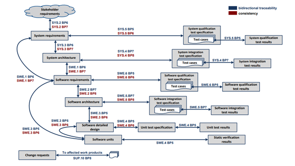
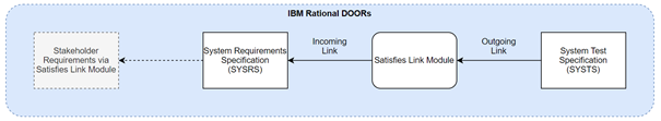
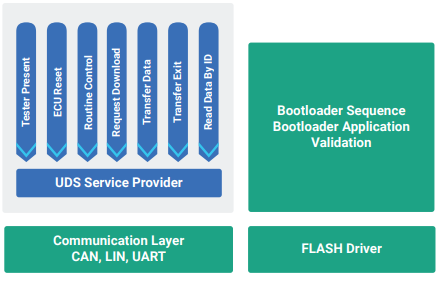
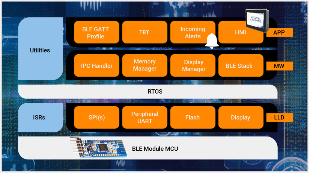
Architecture:
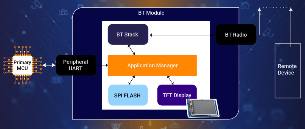
Software Architecture of Bluetooth (BT) Module:
Key Features of the Solution:
- Bluetooth Connectivity – Our solution connects via Bluetooth Low Energy (BLE) to the mobile phone of the driver and sends data to a mobile application. Whenever Bluetooth is enabled, the corresponding icon will be displayed on the TFT screen.
- Calls and Messages – The HMI screen shows all incoming calls, missed calls, SMS notifications, etc.
- Safety Features – Various types of alerts and warnings are also displayed on the HMI screen.
- Turn-By-Turn (TBT) Navigation – Bluetooth connectivity facilitates the navigation data to be transmitted to the digital instrument cluster display screen seamlessly. TBT navigation symbols are displayed at the center of the TFT display when the driver is travelling to the destination. Apart from the directions, the distance to the next turn and remaining distance to destination will also be shown.
- Cloud Connectivity – The digital instrument cluster connects to the cloud and transmits vehicle data. This information is processed in the cloud to derive intelligent insights.
- FOTA Update – We have configured a robust FOTA update feature so that the HMI firmware can be upgraded without any complications.
Optimization for Quick Start-up:
One of the project requirements was that the HMI had to initialize within a short duration, at the time of vehicle start-up. So, we worked on enabling quick start-up of the system and immediate display of the tell tales. Details of the optimization activities:
- Quick Start-up time: The customer required that the start-up is completed within 5 seconds, but we achieved it within 2 seconds.
- Image Update time: As per the requirements, the image update time had to be within 100 milliseconds, but we configured this to be completed within 10 milliseconds.
Overall, TBT images (Read image buffer from flash memory and display them on the screen) was accomplished within 10 milliseconds and Tell-Tales images were displayed within 2 milliseconds.
Embitel Impact
- Our team successfully delivered a cost-effective HMI module and integrated it with the customer’s digital instrument cluster and mobile application.
- The timelines for the completion of this project were very challenging. But due to our prior experience in this type of HMI development projects, we were able to deliver the solution a month ahead of the expected delivery date with undeterred quality.
Tools and Technologies
- Eclipse based IDE – Modus Toolbox