UDS and CAN Stack Integration with Linux Based Telematics Control Unit
Category : Automotive , Product Engineering
About the Customer:
Our customer is a Europe-based Tier 1 supplier developing state-of-the-art connectivity, diagnostics and vehicle telematics solutions. Their powerful, yet flexible, solutions also enable infinite opportunities for custom application development for the automotive industry.
Business Challenge:
Our customer wanted to integrate a UDS software stack on top of CAN stack with their Telematics Control Unit (TCU) to enable vehicle diagnostics functionality. Additionally, the stack could be used for other ECU’s firmware upgrades using secured service and authentication.
The customer purchased our ready-to-deploy UDS and CAN software stacks. However, they needed assistance in integrating these stacks with the Linux OS running on their telematics system.
Our IoT engineering team partnered with the customer to integrate the software stacks on their telematics system and validate the functionalities through elaborate testing.
Embitel Solution:
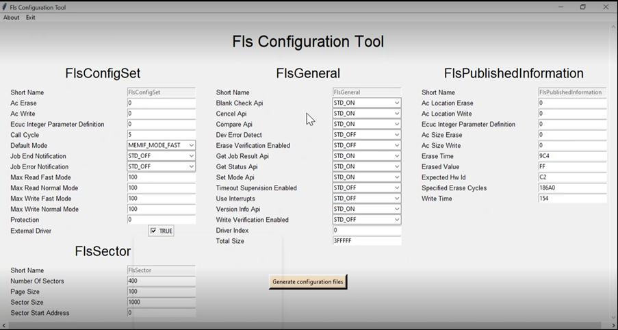
Our UDS and CAN software stacks are hardware-agnostic. However, some customizations are needed when integrating them with various platforms based on the CAN DBC and UDS ODX configurations.
The customer shared the hardware of their telematics system with our engineering team, the required wire harness & debugging equipment. The customer has also shared a skeleton of their integration environment while safeguarding their IP rights.
- In Linux environment, using Yocto, Embitel created a custom layer (meta layer) to incorporate all the proprietary code base and stacks. The meta layer contains libraries, applications, different GUI related applications, etc.
- Recipe libraries were created, which contained details about our source code, its path, how to compile it and how to install it in the customer’s image.
- Embitel cloned the meta layer and integrated it with the existing Yocto source code from the customer.
- Embitel used proprietary tools to generate code from CAN DBC files and UDS ODX files which will reduce manual effort whenever there are changes to configuration files as per the end customer requirements.
- Apart from software stack integration, Embitel also performed system testing and validation of all functionalities of the UDS and CAN stacks.
Ready-to-deploy UDS Stack
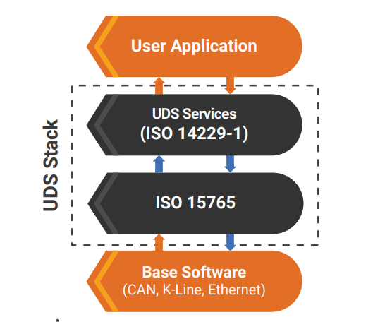
Embitel’s UDS stack enables diagnostics communication between the vehicle ECU and an external diagnostics device.
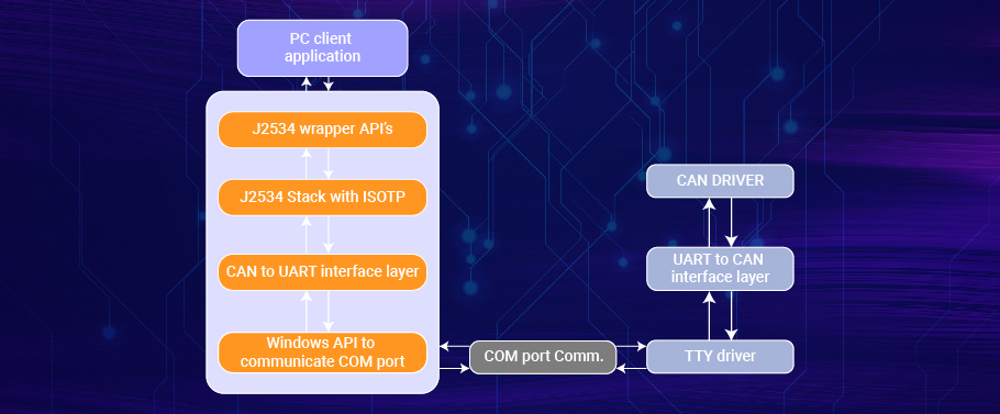
The stack provides a set of APIs to streamline communication between the low-level software and the application software. The communication can be over Ethernet, CAN, K-Line, etc.
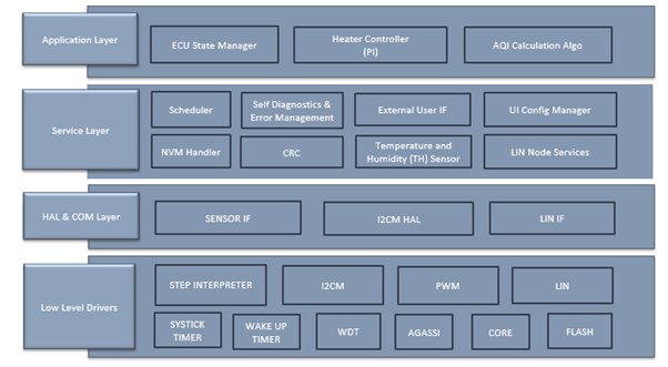
The stack solution consists of the following layers:

The UDS stack is also compliant with ISO 14229 and ISO 15765 standards.
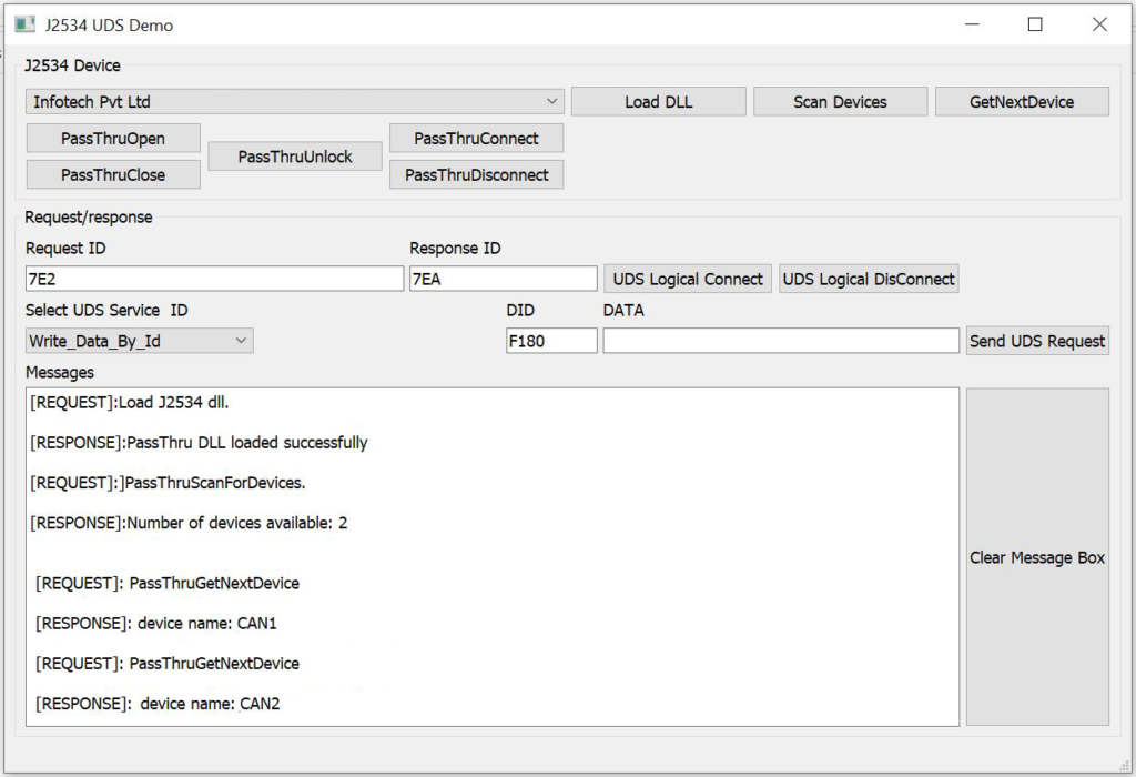
As part of this project, we implemented UDS server functionality, including security authentication of users.
Ready-to-deploy CAN Stack
In automotive solutions that are under development, implementation of our CAN stack enables ECU communication capabilities with reduced turn-around time. The stack is based on ISO 11898 standard and has a modular architecture.
Embitel’s CAN stack is ideal for supporting in-vehicle networking functionalities in passenger vehicles.
Testing:
- PCAN tool and Busmaster tool are used to test all the CAN communications successfully.
- The UDS stack provides multiple services. The customer had requested for 15 UDS services that they wanted to implement. Embitel has successfully integrated UDS stack for all the UDS services, added required glue code to verify specific services End-To-End, and validated the functionalities.
Embitel Impact:
Through the implementation of our UDS and CAN stacks, the customer was able to incorporate various features related to ECU communication and fault diagnostics.
The integration of our stack saved around 4 months of development time for the customer.
Tools and Technologies:
- Linux environment
- Yocto Build tool version Zeus (3.0)
- CANoe for ECU testing and security access validation
- Busmaster for CAN validation
- Project Management tools